1
/
4
-DIN,
1
/
8
-DIN &
1
/
16
- DIN Controllers & Indicators - Product Manual
Page 4 Installation 59305, Issue 5 – March 2005
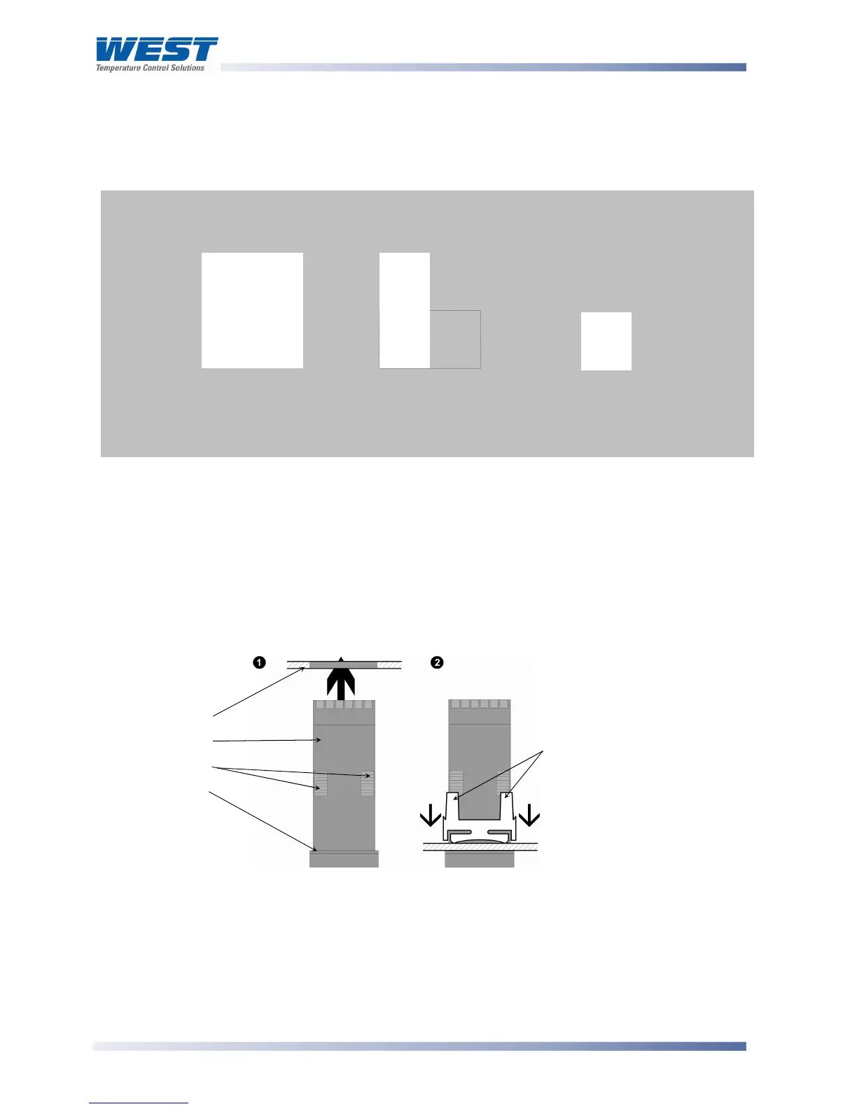
Panel Cut-outs
The mounting panel must be rigid and may be up to 6.0mm (0.25 inches) thick. The cut-outs
required for the instruments are shown below.
Figure 2. Panel cut-out sizes
Panel-Mounting
CAUTION:
Ensure the inside of the panel is with the instruments operating temperature and
that there is adequate air flow to prevent overheating.
Figure 3. Panel-Mounting the instrument
CAUTION:
Do not remove the panel gasket, as this may result in inadequate clamping and
sealing of the instrument to the panel.
1
/
16
DIN
45mm
+0.5 –0.0
1
/
8
DIN
92mm
+0.5 –0.0
(45mm for
indicator)
1
/
4
DIN
92mm
+0.5 –0.0
92mm
+0.5 –0.0
45mm +0.5
0.0
(92mm for indicator)
45mm
+0.5 –0.0
Hold firmly in position
(apply pressure to bezel only)
Mounting Panel
Instrument Housing
Ratchets
Gasket
Slide mounting clamp over the
instrument housing, towards rear face of
mounting panel, until the tongues
engage in ratchets and instrument is
clamped in position
.