1
/
4
-DIN,
1
/
8
-DIN &
1
/
16
- DIN Controllers & Indicators - Product Manual
Page 66 P6700, P8700& P4700 Model Group 59305, Issue 5 – March 2005
P6700, P8700 & P4700 Controllers – Serial Communications Parameters
The Modbus parameter addresses, and the possible ASCII message types and parameters
indents for the P6700, P8700 & P4700 are detailed below. RO indicates a parameter is read
only, R/W indicates it can also be written to. Communications writes will not implemented if
the Communications Write Parameter is disabled. Refer to the Modbus and ASCII
Communications sections of this manual for details of the protocols used.
Bit Parameters
Bit parameters are not applicable to the ASCII protocol.
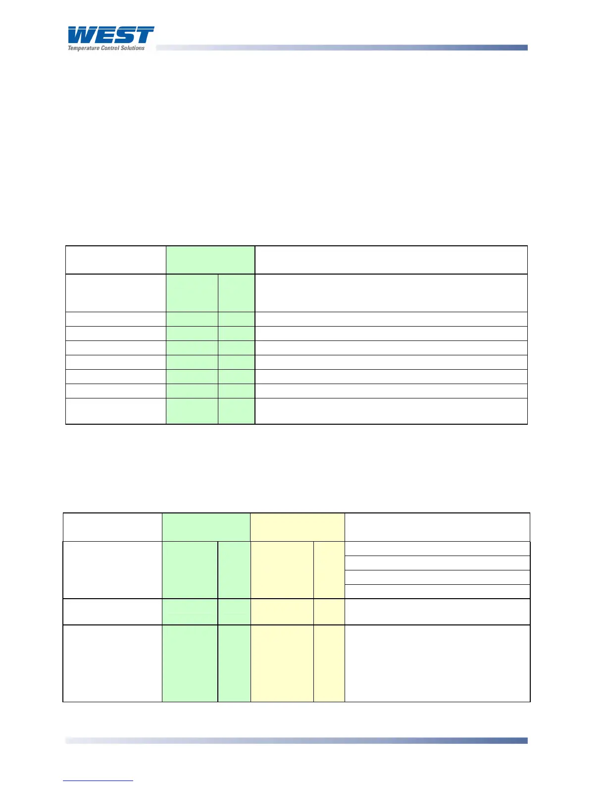
Table 19. P6700, P8700 & P4700 Communications - Bit Parameters
Parameter Modbus
Parameter No.
Notes
Communication
Write Status
1
RO 1 = Write Enabled, 0 = Write Disabled. A negative
acknowledgement (exception code 3) is sent to write
commands if communications writes are disabled
Limit Action
2
RO 1 = Low Limit, 0 = High Limit
Reset Limit Relay
3
R/W 1 = Reset Latched Relays. A read returns the values 0
Limit Status
4
RO 1 =In Exceed Condition, 0 = Not in Exceed Condition
Alarm 1 Status
5
RO 1 = Active, 0 = Inactive
Alarm 2 Status
6
RO 1 = Active, 0 = Inactive
Limit Output Status
7
RO 1 = Relay latched, 0 = Relay not latched
Annunciator Output
Status
8
RO 1 = Active, 0 = Inactive
To set the bit value to 1 write FF, to set the bit value to 0 write 00. Refer to Function Code 05 in the
Modbus Communications section.
Word Parameters
Table 20. P6700, P8700 & P4700 Communications - Word Parameters
Parameter
Modbus
Parameter No.
ASCII Ident &
Message Types
Notes
Current value of PV.
If under-range = 62976 (<??>5 ASCII)
If over-range = 63232 (<??>0 ASCII)
Process Variable
1
RO
M
Type 2
RO
If Sensor break = 63488 (ASCII = n/a)
Limit Setpoint
2
R/W
S
Type 2, 3/4
R/W
Value of the Limit Setpoint.
Hold Value
3
R/W
A
Type 2
RO
Highest PV value (High Limit Action)
or Lowest PV value (Low Limit Action)
since this parameter was last reset.
Modbus: Write any value to reset
ASCII: See Controller Command
00160 for reset.