1
/
4
-DIN,
1
/
8
-DIN &
1
/
16
- DIN Controllers & Indicators - Product Manual
Page 34 Operating and Information Modes 59305, Issue 5 – March 2005
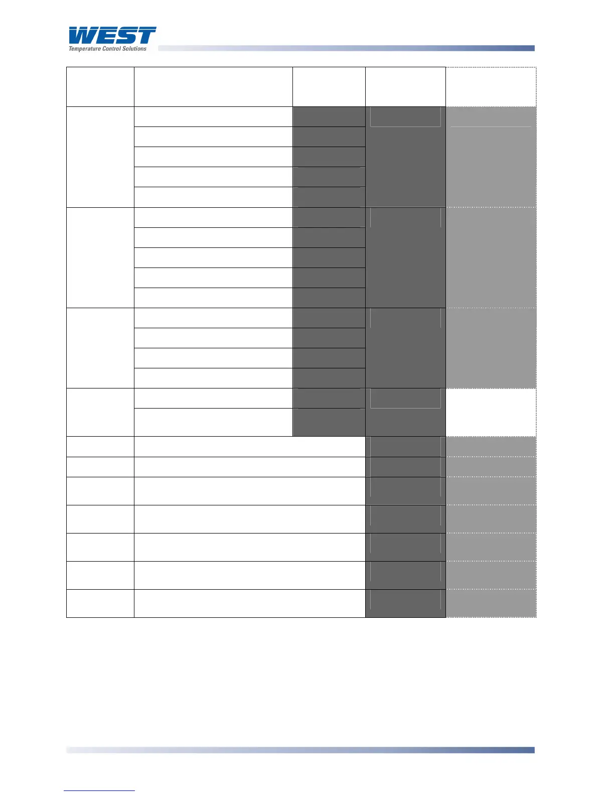
Parameter Possible Values Upper/Main
Display
Lower
Display (or
1
st
Legend)*
1
/
8
DIN
Indicator Units
Display
No option fitted.
%"%.'
Relay
9+C'
SSR drive
::9'
Triac
#9<'
Option 2
module type
Linear voltage / current output
+<%'
,-%3' 3'
No option fitted.
%"%.'
Relay
9+C'
SSR drive
::9'
Linear voltage / current output
+<%'
Option 3
module type
24V Transmitter power supply
D?3E'
,-%4' 4'
No option fitted
%"%;'
RS485 comms
9EFG'
Digital Input
D<!<'
Auxiliary
option A
module type
Basic remote setpoint input
0:-<'
,-%5' 5'
No option fitted
%"%;'
Auxiliary
option B
module type
Full RSP input and
digital input 2
0:-<'
,-%6'
Not Applicable
Firmware
Value displayed is firmware type number
&HI' &'
Issue No.
Value displayed is firmware issue number
AJJ' %'
Product Rev
Level
Value displayed is Product Revision Level.
-0+' 9'
Date of
manufacture
Manufacturing date code (mmyy)
D,Mm'
D'
Serial
number 1
First four digits of serial number
:%2' 5'
Serial
number 2
Second four digits of serial number
:%3' 6'
Serial
number 3
Last four digits of serial number
:%4' ?'
*Note:
On Indicators (which have a single line display), this legend is shown for approx 1 second
before the Main display value.