1
/
4
-DIN,
1
/
8
-DIN &
1
/
16
- DIN Controllers & Indicators - Product Manual
59305, Issue 5 – March 2005 P6100, P8100 & P4100 Model Group Page 43
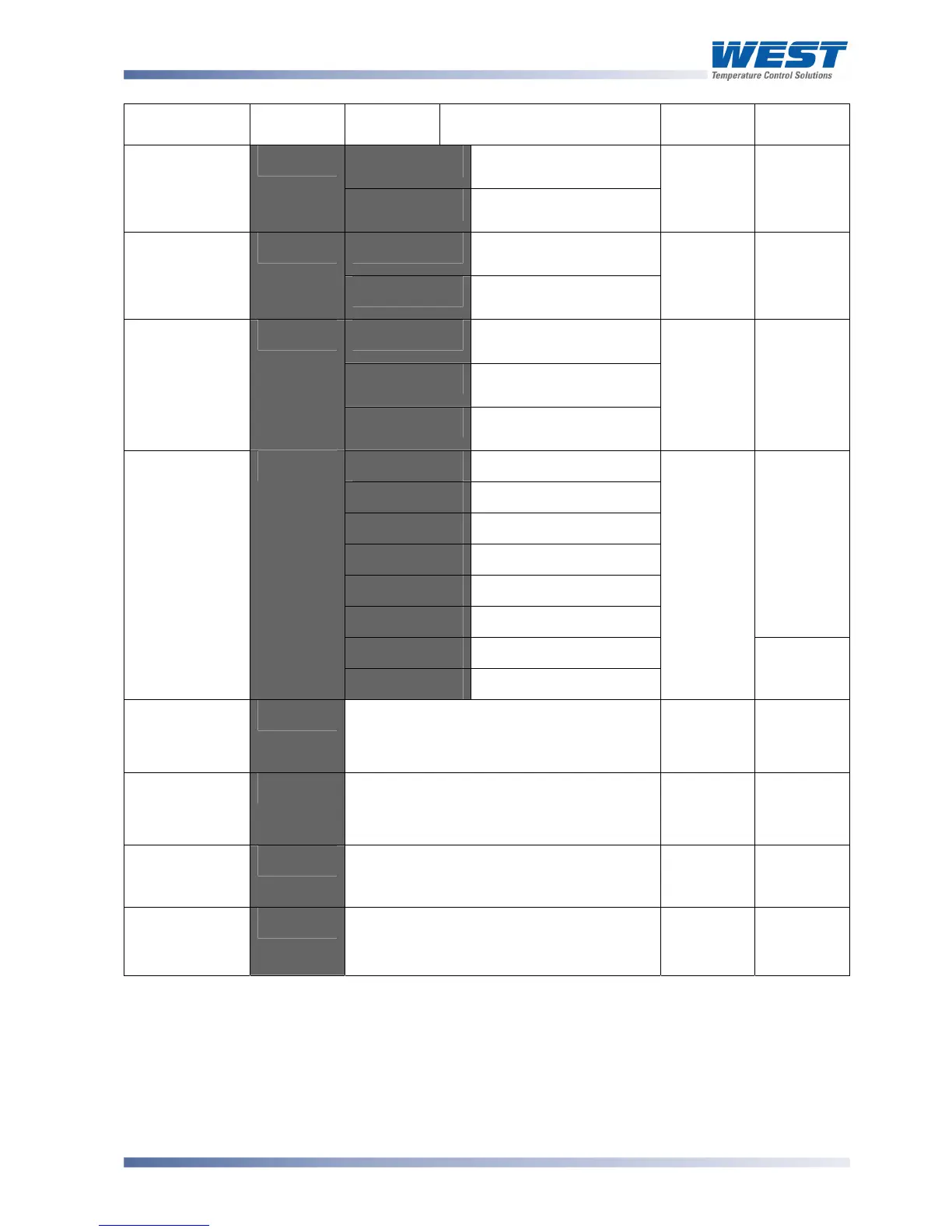
Parameter Lower
Display
Upper
Display
Description Default
Value
When
Visible
r_'o
Read only. Comms
writes ignored
Communica-
tions Write
Enable
$".%'
r_'Ww
Read / Write. Writing via
Comms is possible
r_ Ww
Always
D<:2'
Setpoint 1 / Setpoint 2
Select**
Digital Input 1
Usage
D<!<'
D<5J'
Automatic / Manual
Select**
D<:2'
,1%5
'=
D<!<'
D<:2'
Setpoint 1 / Setpoint 2
Select**
D<5J'
Automatic / Manual
Select**
Digital Input 2
Usage
D<!3'
D<9J'
Remote / Local Setpoint
Select
D<9:'
,1%6
'=
9:-<'
@B3@'
0 to 20mA DC input
EB3@'
4 to 20mA DC input
@B2@'
0 to 10V DC input
3B2@'
2 to 10V DC input
@BG'
0 to 5V DC input
2BG'
1 to 5V DC input
,1%5 or
,1%6
'=
9:-<
2@@'
0 to 100mV DC input
Remote
Setpoint Input
Range
9:-<'
-"#'
Potentiometer (≥2KΩ)
@B2@'
,1%6
'=
9:-<'
Remote
Setpoint Upper
Limit
9:-=' 82777 to 7777'
RSP value to be used when RSP input is
at maximum.
Range
max
,1%5'=
9:-<
Remote
Setpoint Lower
Limit
9:-+' 82777 to 7777'
RSP value to be used when RSP input is
at minimum.
Range min
,1%5'=
9:-<
Remote
Setpoint Offset
9:-"'
Offset applied to RSP value. Constrained
within Scale Range Upper Limit and
Scale Range Lower Limit.
@'
,1%5
'=
9:-<
Configura-
tion Mode Lock
Code
$+"?'
@
to 7777
3@'
Always
*Note:
Alarm parameters marked * are repeated in Setup Mode.
**Note:
If D<!< or D<!3 = D<:2 the remote setpoint input feature is disabled. The instrument
uses the two internal setpoints (SP1 & SP2) instead.
If D<!< and D<!3 are set to the same value, the status of digital input 2 will take
precedence over digital input 1.