1
/
4
-DIN,
1
/
8
-DIN &
1
/
16
- DIN Controllers & Indicators - Product Manual
59305, Issue 5 – March 2005 P6700, P8700& P4700 Model Group Page 49
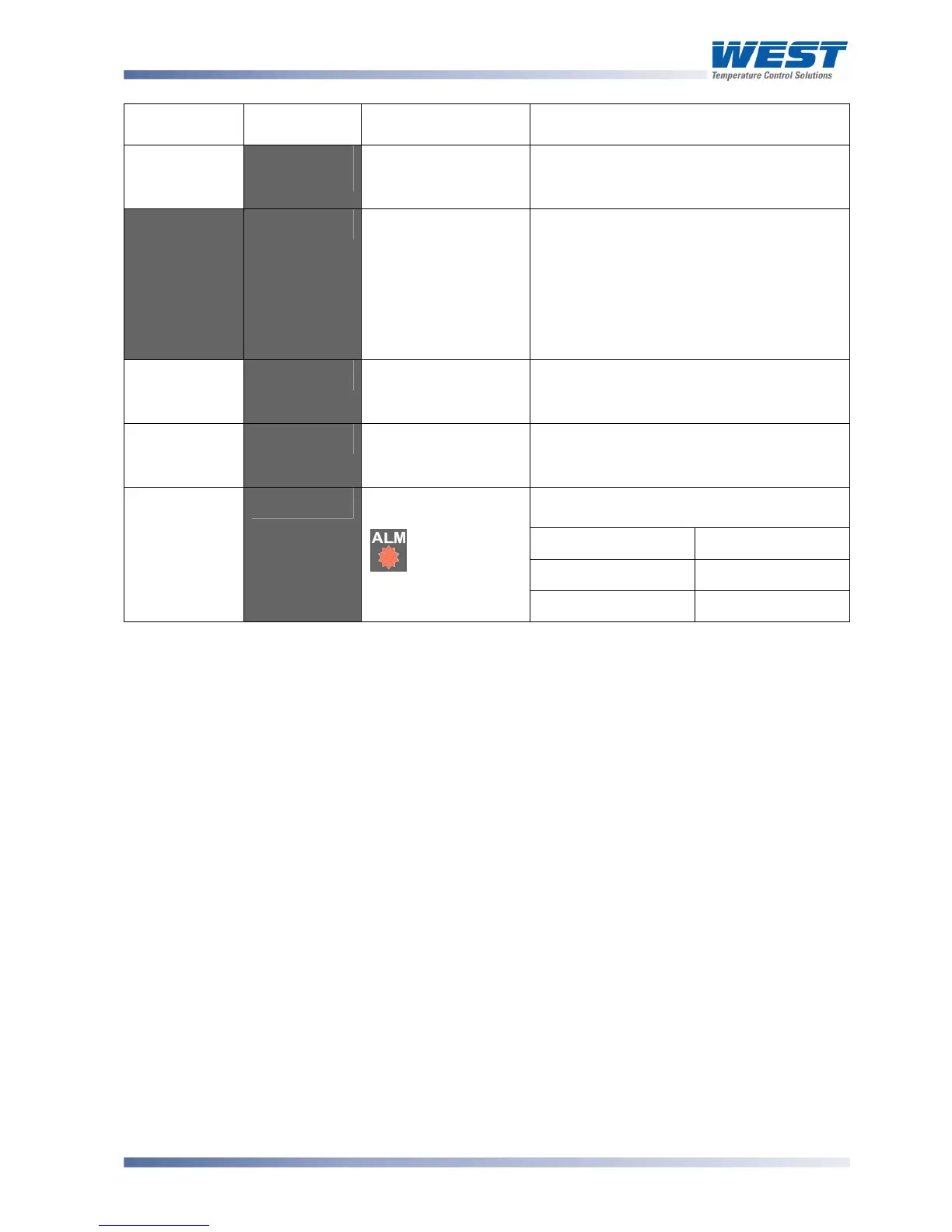
Upper
Display
Lower
Display
When Visible Description
Value
or
*9:-'
D<:O
in config
mode
the active SP (if the digital input has been
overridden, the
_* character is lit instead).
Read only
__+:-'
9:-'
or'
D<!<
:-:'
If Remote Setpoint
Input is fitted, Digital
Input is not
D<:O in
config mode and
::.% is enabled in
Setup mode
Setpoint Select. Selects between Local or
Remote Setpoints.
+:- = local SP, 9:- = remote SP, D<!<
= selection via digital input (if configured).
Note:
+:- or 9:- will override the digital
input (active SP indication changes to
*)
Adjustable except in Strategy 6
Actual SP
Value
:-9-'
If a Ramping
Setpoint is in use
(
9- not Blank).
Actual value of selected Setpoint (e.g.
ramping SP value). Read only
SP Ramp
Rate Value
9-'
If :19 (ramping SP)
is enabled in Setup
mode.
Setpoint ramping rate, in units per hour.
Set to Blank (higher than 7777) to turn off
ramping. Adjustable except in Strategy 6
Upper display shows which alarm(s) are
active. Inactive alarms are blank
'''2'
Alarm 1 Active
''3'
Alarm 2 Active
Active Alarm
Status
5+:#'
When any alarm is
active.
ALM indicator
will also flash
+'
Loop Alarm Active
Note:
When an extended Operator Mode is configured the additional parameters are available
after the above parameters. Extended Operator Mode parameters can only be configured
using the PC software.