1
/
4
-DIN,
1
/
8
-DIN &
1
/
16
- DIN Controllers & Indicators - Product Manual
Page 54 P6100, P8100 & P4100 Model Group 59305, Issue 5 – March 2005
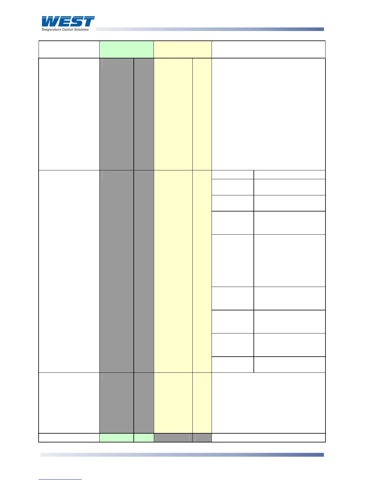
Parameter Modbus
Parameter No.
ASCII Ident &
Message Types
Notes
Controller
commands
Z
Type 3/4
R/W
Only Type 3 / 4 ASCII messages are
allowed with this parameter. The
{DATA} field must be one of eight five-
digit numbers. The commands
corresponding to the {DATA} field
value are:
00010 = Activate Manual Control
00020 = Activate Automatic Control
00030 = Activate the Self-Tune
00040 = De-activate the Self-Tune
00050 = Request Pre-Tune
00060 = Abort Pre-Tune
00130 = Activate Loop Alarm
00140 = De-activate Loop Alarm
Bit Meaning
0 Alarm 1 status.
0 = activated, 1 = safe
1 Alarm 2 status.
0 = activated, 1 = safe
2 Self-Tune status.
0 = disabled
1 = activated
3 Change Indicator. 1 =
A parameter other than
controller status, PV or
Output power has been
changed since the last
time the status word
was read.
4 Comms write status:
0 = disabled
1 = enabled.
5 A/M control.
0 = disabled
1 = enabled
7 Pre-tune status.
0 = disabled
1 = enabled.
Controller Status
L
Type 2
RO
8 Loop alarm status.
0 = activated, 1 = safe.
Scan Table
]
Type 2
RO
Reads back main process values.
Response is: L{N}25aaaaabbbbb
cccccdddddeeeeeA* where:
aaaaa = Actual Setpoint value
bbbbb = Process Variable value
ccccc = Primary PID Power value
ddddd = Secondary PID Power value
eeeee = Controller Status (see above)
Equipment ID
122
RO
The four digit model number 6100