1
/
4
-DIN,
1
/
8
-DIN &
1
/
16
- DIN Controllers & Indicators - Product Manual
59305, Issue 5 – March 2005 P6700, P8700& P4700 Model Group Page 61
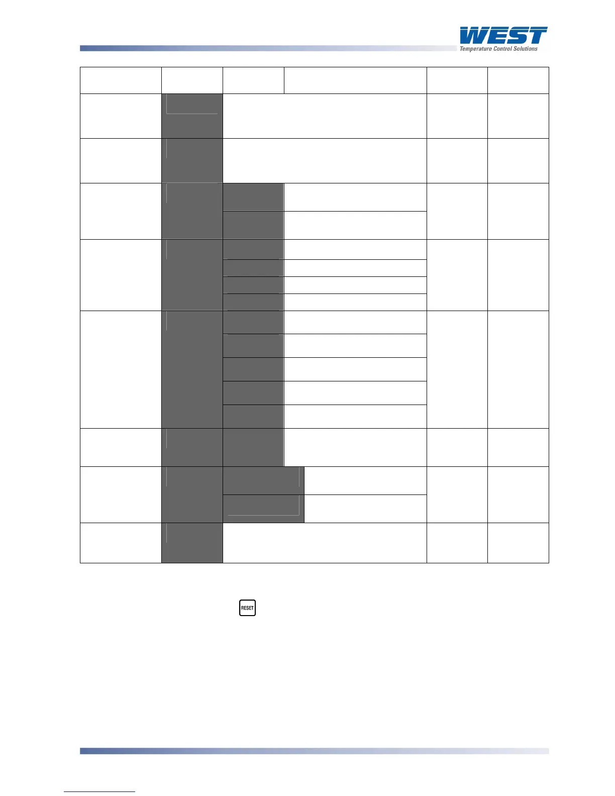
Parameter Lower
Display
Upper
Display
Description Default
Value
When
Visible
Retransmit
Output 3 Scale
maximum
9"4)'
82777
to 7777'
Display value where output is maximum
Range
max
>J;4'=
9;#: or
9;#-
Retransmit
Output 3 Scale
minimum
9"4+' 82777 to 7777'
Display value where output is minimum
Range min
>J;4'=
9;#: or
9;#-
.%56'
PV is visible in Operator
mode
Display
Strategy
D<J1'
D<:5'
PV not visible in Operator
mode
.%56
Always
5:$A'
ASCII
Mm6%'
Modbus with no parity
Mm6.'
Modbus with Even Parity
Comms
Protocol
-9"#'
Mm6"'
Modbus with Odd Parity
Mm6%'
,1%5'=
9EFG'
2. 3'
1.2 kbps
3. E'
2.4 kbps
E. F'
4.8 kbps
7. P'
9.6 kbps
Bit rate
65=D'
27. 3'
19.2 kbps
E. F'
,1%5
'=
9EFG'
Communica-
tions Address
5DD9'
'2'
A unique address for each
instrument between 1 to 255
(Modbus), or 1 to 99 (Ascii)
2'
,1%5
'=
9EFG'
r_'o
Read only. Comms
writes ignored
Communica-
tions Write
Enable
$".%'
r_'Ww
Read / Write. Writing via
Comms is possible
r_ Ww
Always
Configuration
Mode Lock
Code
$+"?'
@
to 7777
3@'
Always
Notes:
Option Slot 1 is a fixed Limit Relay output. A Digital Input module fitted to Option Slot A will
duplicate the front Reset key function.
As these functions cannot be changed, configuration menus are not required.
Alarm parameters marked * are repeated in Setup Mode.
CAUTION:
Process Variable Offset can be used to modify the measured value to compensate
for probe errors. Positive values increase the reading, negative values are
subtracted. This parameter is effectively, a calibration adjustment and MUST be
used with care.