1
/
4
-DIN,
1
/
8
-DIN &
1
/
16
- DIN Controllers & Indicators - Product Manual
59305, Issue 5 – March 2005 P6010 & P8010 Model Group Page 73
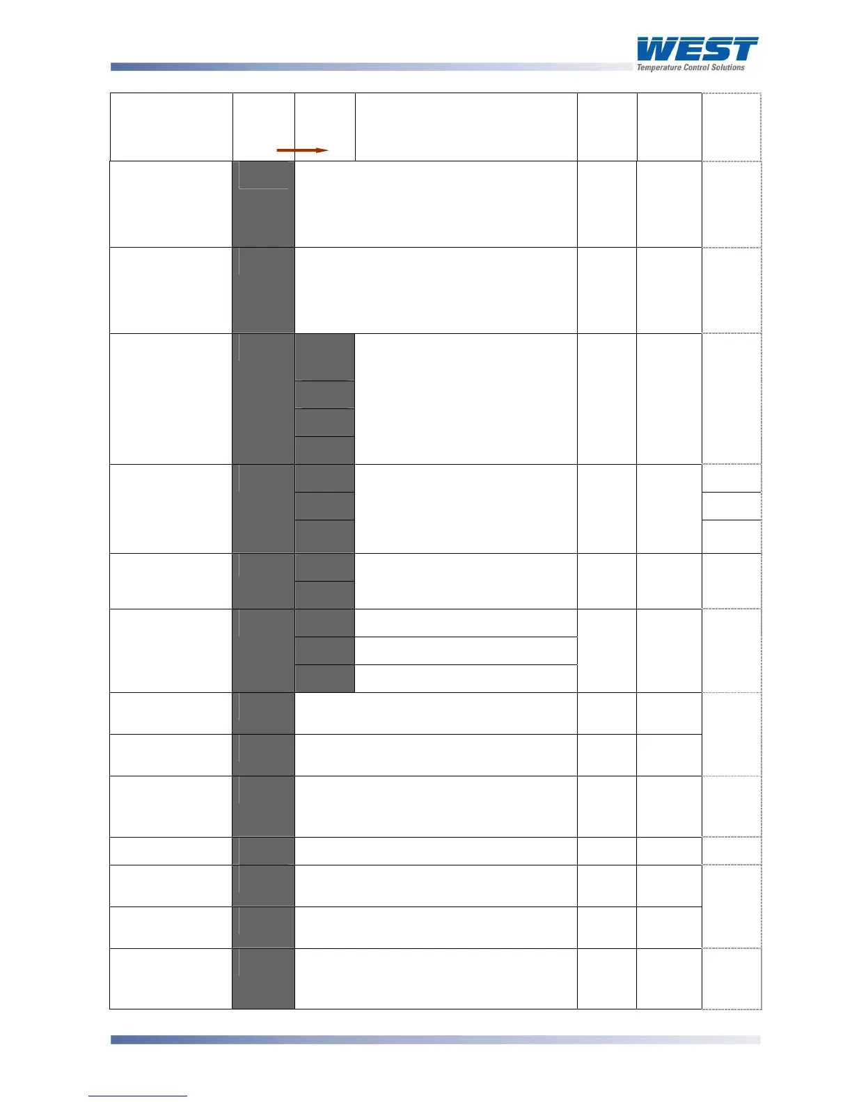
Parameter
Legend
for 1 sec
followed
by
Set
Value
Adjustment Range &
Description
Default
Value
When
Visible
Units
Display
(
1
/
8
Din
Only)
Scale Range
Upper Limit
9=+'
Scale Range Lower Limit +100 to Range
Max
Linear
= 1000
°C/°F
= max
range
Always
='
Scale Range
Lower Limit
9++'
Range Min. to Scale range Upper Limit -
100
Linear
= 0
°C/°F
= min
range
Always
+'
''@
''
'2'
'3'
Decimal point
position
D-":'
'4'
Decimal point position in non-
temperature ranges.
0 = XXXX
1 = XXX.X
2 = XX.XX
3 = X.XXX
2'
A%1K
'
= mV, V
or mA
'
-'
%"%.'
'
$'
°
$
'
Linear Range
Engineering
Units Display
+<%>'
&'
%"%.
(Blank), $ = °C or & = °F
For use where linear inputs
represent temperature.
Available on
1
/
8
Din units only.'
%"%.'
1
/
8
Din
only.
A%1K'
= mV, V
or mA
'
°
&
'
.%56'
Multi-Point
Scaling
Mm-:'
D<:5'
D<:5
'disabled or
.%56 enabled
D<:5'
Always
:'
-B)<'
Process High Alarm
-B+"'
Process Low Alarm
Alarm 1Type
5+52'
%"%.'
No alarm
-B)<'
Always
2'
Process High
Alarm 1 value*
-N52'
Range Min. to Range Max.
Parameter repeated in Setup Mode
Range
Max.
5+52'
= -B)<
Process Low
Alarm 1 value*
-+52'
Range Min. to Range Max
Parameter repeated in Setup Mode
Range
Min.
5+52'
= -B+"'
5 if
alarm
1 only
or
2'
Alarm 1
Hysteresis*
5)M2'
1 LSD to 100% of span (in display units)
on “safe” side of alarm point.
Parameter repeated in Setup Mode
2'
5+52
is not
%"%.
B'
Alarm 2 Type
5+53'
As for alarm 1 type
%"%.'
Always
3'
Process High
Alarm 2 value*
-N53'
Range Min. to Range Max.
Parameter repeated in Setup Mode
Range
Max.
5+53'
= -B)<
Process Low
Alarm 2 value*
-+53'
Range Min. to Range Max.
Parameter repeated in Setup Mode
Range
Min.
5+53'
= -B+"'
3'
Alarm 2
Hysteresis*
5)M3'
1 LSD to 100% of span (in display units)
on “safe” side of alarm point.
Parameter repeated in Setup Mode
2'
5+53
is not
%"%.
S'