1
/
4
-DIN,
1
/
8
-DIN &
1
/
16
- DIN Controllers & Indicators - Product Manual
59305, Issue 5 – March 2005 P6010 & P8010 Model Group Page 75
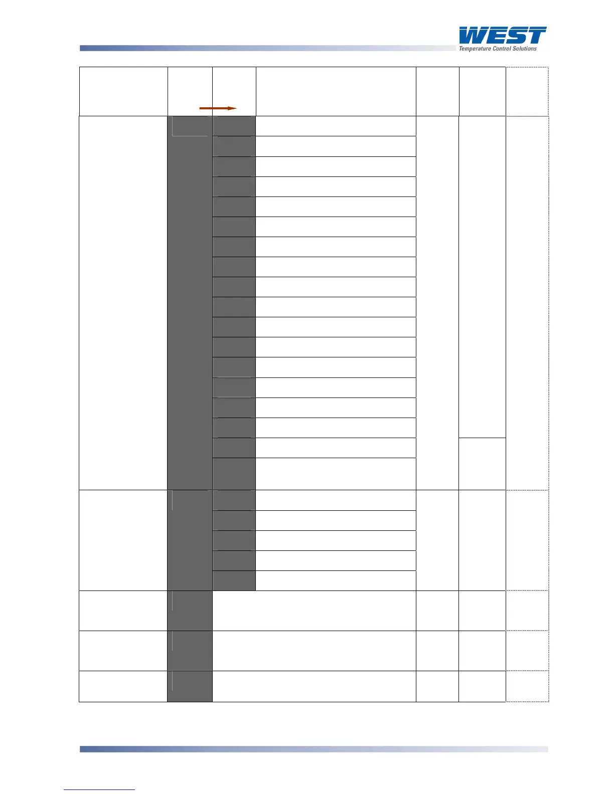
Parameter
Legend
for 1 sec
followed
by
Set
Value
Adjustment Range &
Description
Default
Value
When
Visible
Units
Display
(
1
/
8
Din
Only)
5E%D'
Alarm 4, direct, non-latching
5E%9'
Alarm 4, reverse, non-latching
5E+D'
Alarm 4, direct, latching
5E+9'
Alarm 4, reverse, latching
5G%D'
Alarm 5, direct, non-latching
5G%9'
Alarm 5, reverse, non-latching
5G+D'
Alarm 5, direct, latching
5G+9'
Alarm 5, reverse, latching
,23D'
Logical Alarm 1 OR 2, direct
,239'
Logical Alarm 1 OR 2, reverse
,24D'
Logical Alarm 1 OR 3, direct
,249'
Logical Alarm 1 OR 3, reverse
,34D'
Logical Alarm 2 OR 3, direct
,349'
Logical Alarm 2 OR 3, reverse
5%MD'
Any active alarm, direct
5%M9'
Any active alarm, reverse
9;#-'
Retransmit PV Output
'
D?2,'
0 to 10VDC (adjustable)
transmitter power supply*
'
,1%2 is
linear
output
type
@BG'
0 to 5 V DC output 1
@B2@'
0 to 10 V DC output
3B2@'
2 to 10 V DC output
@B3@'
0 to 20 mA DC output
Output 1 PV
Retransmit Type
#C-2'
EB3@'
4 to 20 mA DC output
@B2@'
>:.2 =
9.#-
2'
Retransmit
Output 1 Scale
maximum
9"2)'
82777
to 7777'
Display value where output is maximum
Range
max
>J;2 =
9;#-'
)'
Retransmit
Output 1 Scale
minimum
9"2+' 82777 to 7777'
Display value where output is minimum
Range
min
>J;2 =
9;#-'
+'
Output 1 TxPSU
voltage level
-:>2'
0 to 10VDC transmitter power supply
output in 0.1V steps*
2@.@'
>J;2
=
D?2@'
2'