1
/
4
-DIN,
1
/
8
-DIN &
1
/
16
- DIN Controllers & Indicators - Product Manual
59305, Issue 5 – March 2005 P6010 & P8010 Model Group Page 77
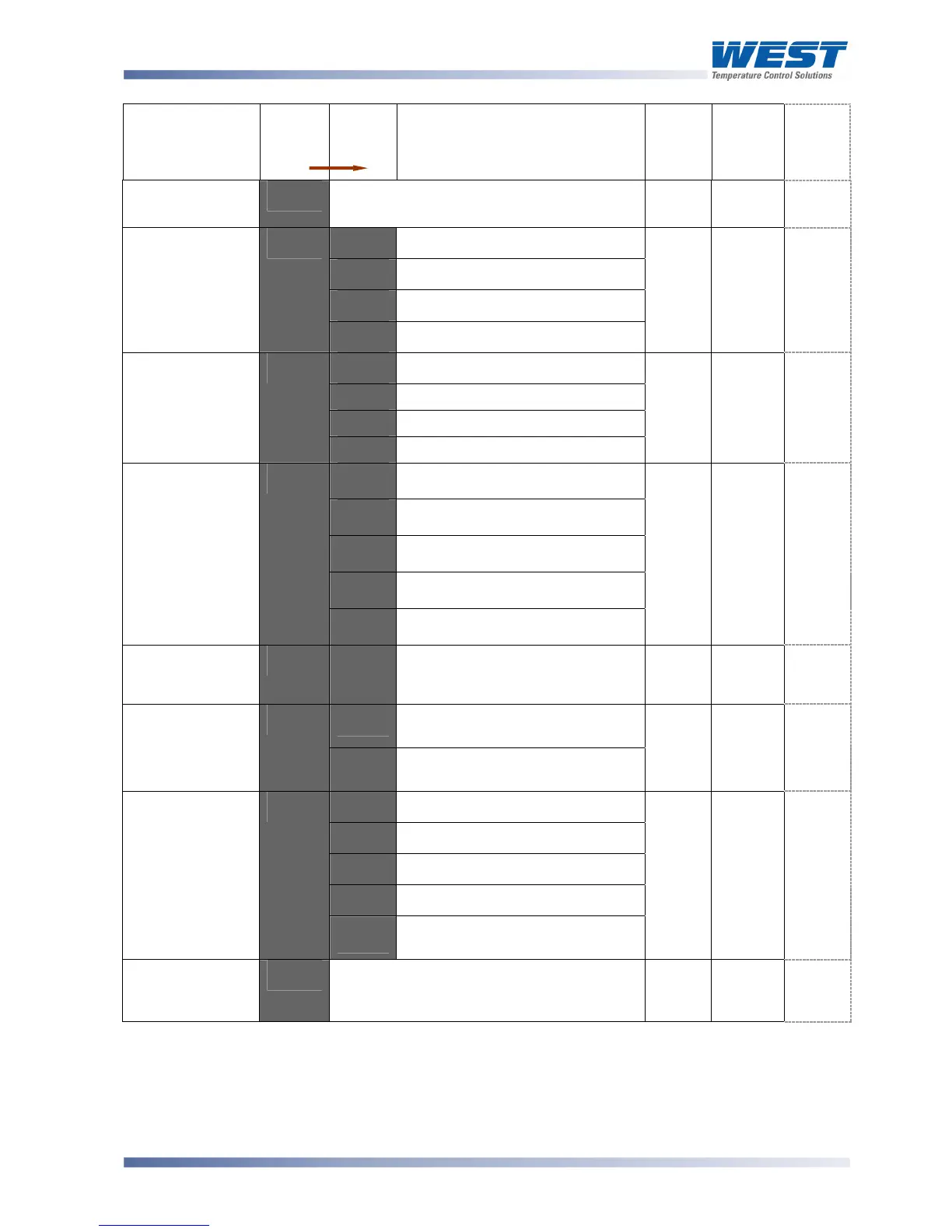
Parameter
Legend
for 1 sec
followed
by
Set
Value
Adjustment Range &
Description
Default
Value
When
Visible
Units
Display
(
1
/
8
Din
Only)
Display Strategy
D<J1'
@,'2,'3,'4,'E or P'
(see Operator Mode for details)
@'
Always
D'
9.D'
Permanent Red
!9%'
Permanent Green
98!'
Red to Green if any alarm active
Display Colour
$+"9'
!89'
Green to Red if any alarm active
!89'
1/8 Din
units if
colour
change
display
fitted
?'
5:$A'
ASCII
Mm6%'
Modbus with no parity
Mm6.'
Modbus with Even Parity
Comms Protocol
-9"#'
Mm6"'
Modbus with Odd Parity
Mm6%'
,1%5'
=
9EFG
-'
2. 3'
1.2 kbps
3. E'
2.4 kbps
E. F'
4.8 kbps
7. P'
9.6 kbps
Bit rate
65=D'
27. 3'
19.2 kbps
E. F'
,1%5
'
=
9EFG
6'
Communica-
tions Address
5DD9'
'2'
A unique address for each
instrument between 1 to 255
(Modbus), or 1 to 99 (Ascii)
2'
,1%5
'
=
9EFG
5'
r_'o
Read only. Comms writes
ignored
Communica-
tions Write
Enable
$".%'
r_Ww'
Read / Write. Writing via
Comms is possible
r_ Ww
Always
.'
99+M'
Reset latched relay(s)
#59.'
Initiate Tare (zero display)
9-='
Reset min/max PV values
9.'
Reset Alarm 1 elapsed time
Digital Input
Usage
D<!<'
9-=.'
Reset Alarm 1 elapsed time
& min/max PV values
99+M'
,1%5
'
=
D<!<
<'
Configuration
Mode Lock
Code
$+"?'
@
to 7777
3@'
Always
$'
Note:
*Linear Outputs can be configured to provide an adjustable 0.0 to 10.0VDC transmitter
power supply for external devices. This is an alternative to the fixed 24V Transmitter
Power Supply option module.