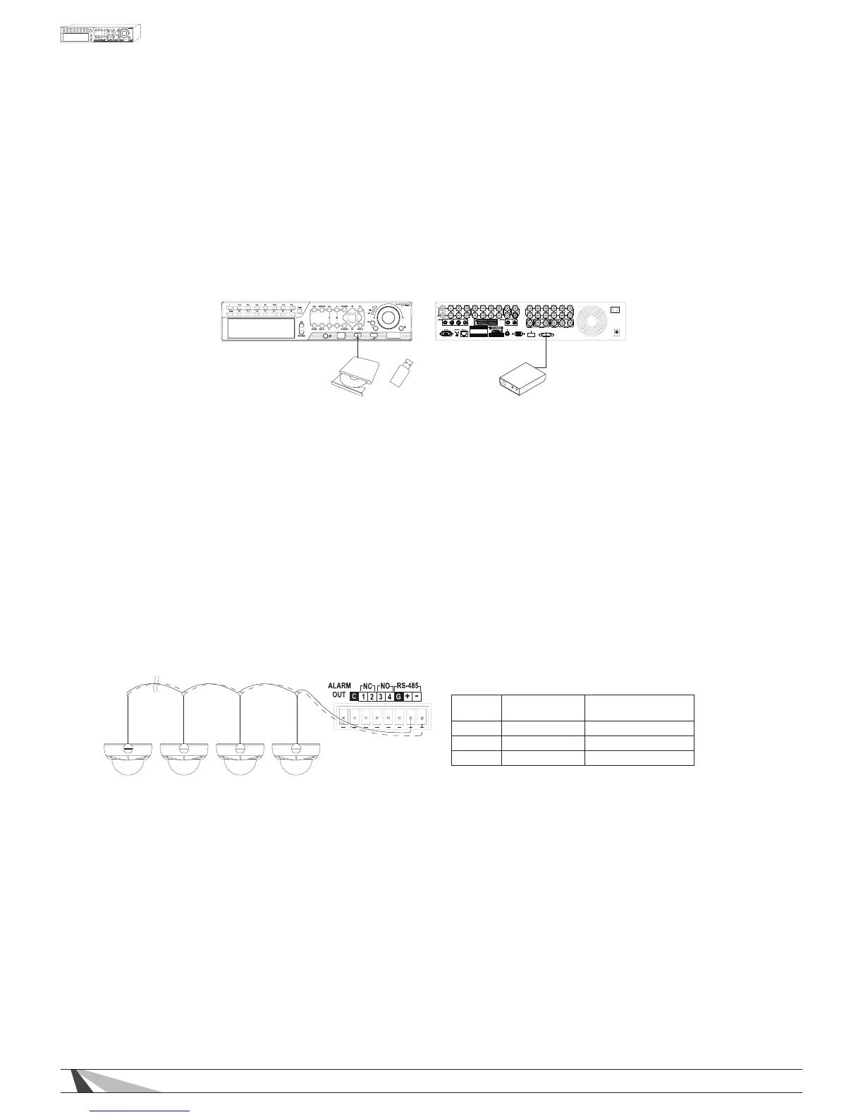
•ALARMOUTPUT
Connect the alarm output to either a NC or NO type of device or system.
•ETHERNET
Connect the Ethernet connector to router via a standard Ethernet cable for control and streaming to an
Automation System, remote access via PC or Smartphone, or event email notications. Please make sure to
setup the related congurations as described in Section 6.11 Network Setup.
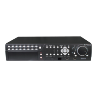
•USB2.0
External storage devices such as a USB thumb drive can be connected for archiving recorded content.
Content cannot be recorded directly to a USB Drive.
VGA
HDMI
ESATA
ALARM
OUT
G
G
G
G
-
+
G
RS-485
C
DC12V
POWER
External ESATA
Hard Disk Drive
Thumb DriveDVD+RW OR
•ESATA
Connect an ESATA enclosure to easily expand your daily recording time. The enclosure must be set up in a
JBOD array and be self powered.
•CAMERALOOPOUTPUTS
Connect the BNC loop outputs to a dedicated local display (Sometimes referred to as Spot Monitors), video
distribution system, or Automation system touch panel.
3.2.3. PTZ CAMERA / AUTOMATION SYSTEM CONNECTIONS
•PTZCAMERAS
Connect the RS-485 connector to PTZ camera(s) via an appropriate cable. The system supports a variety
of PTZ cameras and the OSD menu of Wirepath™ Surveillance cameras. Different PTZ cameras can coexist
in a system only if they support the same protocol and baud rate. Make sure to set unique PTZ IDs to the
cameras, the DVR and any other PTZ device. Setup each camera (Section 6.1), and RS-485 (Section 6.10)
accordingly.
For PTZ Devices
For Wirepath
Surveillance Cameras
RS-485 + RxD + (Data +) Positive +
RS-485 - RxD + (Data -) Negative -
GND GND No Connection
 Loading...