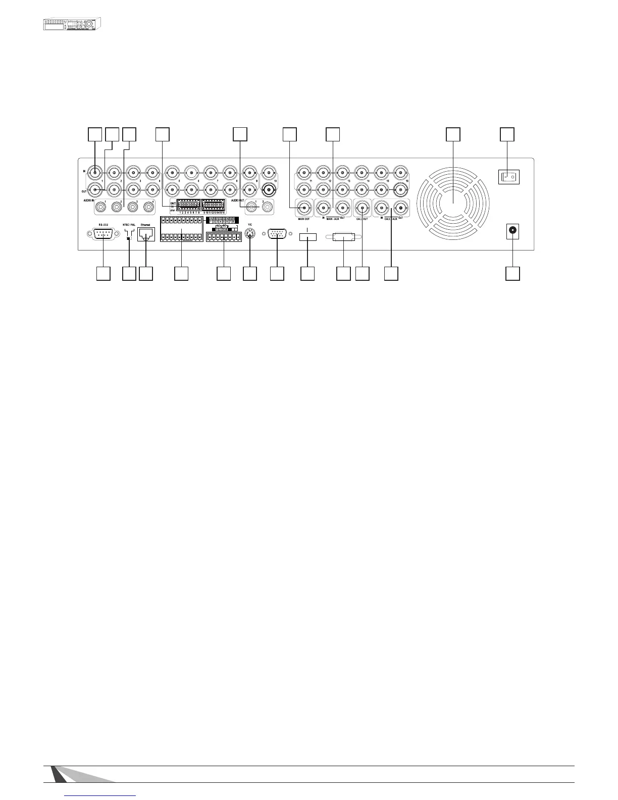
2.2. REAR PANEL
1 2 3 4
5
6a 7 8 9
1011121314156b1617181919
VGA
HDMI
ES ATA
ALARM
OUT
G
G
G
G
-
+
G
RS-485
C
DC 12V
POWER
1. Video Input Connectors (1-9 on WPS-300-DVR-9CH, 1-16 on WPS-300-DVR-16CH)
Connect system cameras to these BNC connectors. The corresponding 75 Ω termination must be ON unless
the video output terminal is connected. See item 5 below.
2. Video Output Connectors (1-9 on WPS-300-DVR-9CH, 1-16 on WPS-300-DVR-16CH)
BNC connectors for looping camera output from the corresponding camera video input. The
corresponding 75 Ω termination must be ON unless the video output terminal is connected. See item 5
below.
3. Audio Input Connectors (AUDIO IN 1-4)
RCA connectors for line-in audio signals supplied from external devices such as microphone ampliers.
4. Audio Output Connectors (AUDIO OUT 1-2)
Supplies line-out audio signals to external devices such as ampliers. Recorded audio will be supplied from
AUDIO OUT during playback.
5. Video Loop Dip Switches
Set each of the DIP switches to ON unless the corresponding video output terminal is connected. The
following are the camera inputs for looping:
No Loop to Output- ON(Up)
Loop Output- OFF (Down)
NOTE: Leave these switches ON if no loop out device is connected. Having no active connection can
cause a brightened “over-voltage” image.
6. Main Monitor Output Connectors (6a - BNC MAIN OUT, 6b - Y/C (S-Video) MAIN OUT)
Connection to TV monitors via mini-din S-video connector or BNC connector for main monitor display.
7. MAIN-AUX Connectors (MAIN-AUX IN/OUT)
These connections are not functional on this model.
8. Cooling Fan
Internal power supply exhaust fan to provide cooling to the unit. When installing, please leave room behind
the unit in order to maintain a proper operating temperature.
9. Power Switch (POWER)
Main power for the unit.
NOTE: Before turning the power OFF, select SHUTDOWN from the MENU and allow time for the hard drives
to properly shutdown. Hard drive damage may occur if the unit is not shut down from the MENU.
 Loading...