3-15Maintenance
16-1408348
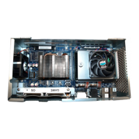
8 Insert the two security screws removed in step 1 on page 3-13 into the Board Bracket,
Figure 3-33 (A).
Figure 3-33 Insert the two security screws into the Board Bracket.
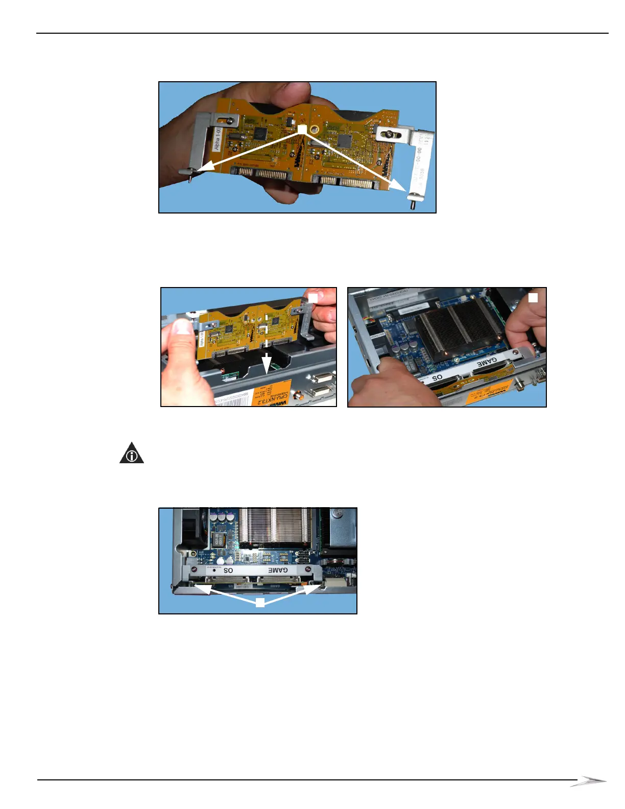
9 Holding the edges of the Board Bracket, Figure 3-34 (A), position the Board Bracket so that the
screw holes in the Board Bracket line up with the screw holes in the CPU, carefully place the
board and bracket onto the CPU, Figure 3-34 (B).
Figure 3-34 Hold edges of PATA Board bracket (left) and lift board and bracket onto CPU (right).
10 Using a T10 Security Torx screwdriver, tighten the two security screws, Figure 3-35 (A), that
secure the PATA Board and bracket to the CPU.
NOTE: The right security screw is located between the audio jack and the DVI connector, and
the left security screw is located on the edge of the PATA Board between the faceplate input
connector and the power connector.
Figure 3-35 Tighten the two security screws.
 Loading...