Do you have a question about the Wood-mizer LT40L DH and is the answer not in the manual?
Details VIN and model number for sawmill identification.
Explains VIN locations on the machine and details of each VIN digit.
Explains the LT40 base model ID and E25 engine/motor configuration.
Explains safety symbols (DANGER, WARNING, CAUTION) and general safety advice.
Safety measures for handling saw blades, including protective gear and keeping others away.
Safety advice on securing the mill, incline limits, and tensioner effects.
Covers guards, moving parts, operator safety, PPE, and loose clothing.
Checks for power feed, log clamping, and board return operation.
Guidelines for using the board return table and water lube accessory.
Ensuring clearance and preventing damage during log loading.
Safety for electrical systems, repairs, connectors, and boxes.
Risks associated with open boxes, water ingress, and power disconnection.
Ensuring power is off and clear workspace for maintenance.
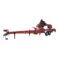
Safety for decals, towing, and securing the cutting head.
Cautions regarding drum switch grease, mast rail grease, and chain lube.
Warnings against over-tensioning chains and importance of stop bolt adjustment.
Adjusting pad spacing and risks of over-tightening.
Pictograms for reading manual and ensuring guards are closed.
Pictogram illustrating blade tension adjustment.
Pictograms for blade tension and maintaining safe distance.
Pictogram warning about the debarker blade hazard.
Pictograms related to electrical box operation and power supply.
Pictograms for sawdust outlet and trailer safety.
Pictogram indicating blade movement direction.
Pictograms for chain care and wearing eye protection.
Pictograms for hearing protection and footwear safety.
Pictogram indicating a lubrication point.
Pictograms for blade alignment and safety certifications.
Pictogram showing motor rotation direction.
Ensuring safety during towing, securing hitch and cable.
Table detailing belt sizes and part numbers for the LT40 sawmill.
Recommendations for blade types based on wood and power.
Chart of recommended blade sizes and part numbers.
Maximum log diameter and length with bed extensions.
Information on peak cutting rates and conditions.
Details on available engine and motor power options.
Specs for power feed, up/down, and hydraulic motors.
Comparison of noise levels for gas and electric sawmills.
Physical dimensions and weight data for the sawmill.
Load capacity specifications for the sawmill chains.
Details on the hydraulic pump and pressure ratings.
Airflow, motor power, and sack capacity of the dust extractor.
Safety requirements for grounding, startup, and vibration.
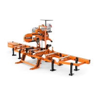
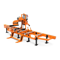
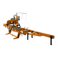
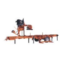
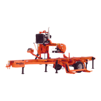
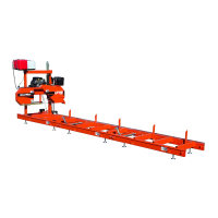
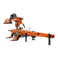
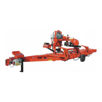
Illustration and list of major sawmill components.
Electrical diagram for the hydraulic pump system.
Essential conditions to meet before operating the sawmill.
Requirements for the setup area and ensuring the mill is level.
Fastening the mill and initial operational steps.
Safety measures for inclines, chocking wheels, and trailer support.
Steps for unhitching and lowering outriggers.
Detailed steps for adjusting the outriggers.
Precautions for setting up on soft or boggy ground.
Steps for handling carriage chain, cutting head, and fenders.
Lowering rear outriggers and raising side supports.
Cleaning, soaking wiper, installing cover, and avoiding binding.
Safety during blade removal and steps for removal.
Installation guidelines and warning about pinching fingers.
Steps for tensioning using the handle and a table of values.
Impact of temperature on tension and caution for storage.
Steps for initial positioning and safety checks.
Specific measurements and cant control use for tracking.
Reminder to ensure guards and covers are in place.
Ensuring safety before starting, including electrical box hazards.
Keeping the electric box clean and setting the time-delay relay.
Procedure to change motor rotation direction if incorrect.
Requirements for levers to be operational and power connection.
Safety precautions for the hydraulic pump power control box.
Verifying operation of switches, indicators, and safety features.
Diagram of control levers and safety for log loading.
Procedures for adjusting clamp, loader, and turner arms.
How to adjust toe boards for leveling tapered logs.
Steps for preparing and safely loading logs.
Process for centering, loading logs, and arm placement.
Procedures for turning logs, including optional methods.
Methods for clamping logs and available clamp types.
Using toe boards to level tapered logs accurately.
Checking blade tension and setting cutting head height.
Using the switch and respecting travel limits.
Adjusting the outer guide to clear the log's widest section.
Keeping the blade guide close to the log during cuts.
Ensuring safety and performing checks before operation.
Location and basic function of the clutch/brake lever.
Steps for engaging and disengaging the sawmill blade.
Description of the two switches on the control panel.
How to operate the speed and direction controls.
Importance of keeping the power feed switch in neutral.
Safety for the power feed switch and starting cuts.
How to stop the carriage and blade safely.
Safe movement practices and clearing log ends.
Steps before the first cut: placement, clamping, height, guards.
Feeding into the log and adjusting feed rate.
Actions at the end of a cut and for returning the carriage.
Adjusting supports and stacking boards for edging.
Steps for edging and flipping boards.
Safety for leaving the blade engaged during carriage return.
Description of the scale's indicator, inch, and quarter scales.
How to use the indicator and avoid parallax error.
Understanding how the inch scale indicates blade height.
Details on quarter scales and choosing the right one.
Example demonstrating how to use the quarter scale for cuts.
How the system works and when to use it.
Safety warning about fluids and blade cleaning steps.
Handling the system in freezing temperatures.
Initial steps for towing and outrigger safety.
Adjusting the clamp for safe transport.
Adjusting components for ground clearance and positioning.
Procedures for seating and securing the saw head.
Critical adjustment for carriage security during transport.
Securing loader/turner and engaging clutch for transport.
Attaching and ensuring carriage safety chain is secure.
Storing loose items and placing fenders for travel.
Adjusting outriggers for safe towing.
Guidance to consult the trailer manual.
Explanation of short interval vs. log-based maintenance.
Estimated lifespan for common replacement parts.
Checking rollers for wear and adjusting blade screw.
Cleaning sawdust from housings, valves, and belt covers.
Cleaning, lubrication, and adjustment of track components.
Cleaning mast rails and warnings against using grease.
Lubricating switch contacts and warning about grease contents.
Lubricating various points and oiling chains.
Checking alignment and maintaining safety decals.
Lubricating tensioner rods and screw handle.
Steps for adding and filling hydraulic fluid.
Procedures for checking belt wear and replacement.
When and why to inspect and adjust the brake strap.
Steps for adjusting the brake strap.
Checking belt tension and adjusting manual clutch.
Procedure for adjusting belts with autoclutch.
Adjusting throttle cable and checking belt wear.
Purpose of the support and how to adjust it.
Steps before adjustment: blade removal, guard removal, measurement.
Adjusting the turnbuckle for correct pivot alignment.
Checking fluid, replacement intervals, and temperature effects.
Procedure for replacing the hydraulic system filter.
Periodic inspection of hydraulic lines and fittings.
Procedure for refilling fluid in the bearing housing.
Up/down system belt design and chain tensioning.
Safety for securing the head and cautions on chain tensioning.
Procedures for adjusting the power feed belt and chain.
Tasks listed for blade change, 8-hour, and 25-hour intervals.
Log entries for maintenance performed at 50 to 500 hour intervals.
Log entries for maintenance performed at 550 to 1000 hour intervals.
Log entries for maintenance performed at 1050 to 1500 hour intervals.
Log entries for maintenance performed at 1550 to 2000 hour intervals.
Causes and solutions for dull or breaking blades.
Troubleshooting blade tracking and guide problems.
Addressing drive belt wear and bearing problems.
Troubleshooting thickness variation and lumber squareness.
Addressing sawdust on track and wavy cut causes.
Troubleshooting slow or non-working up/down motors.
Troubleshooting power feed motor faults and short circuits.
Diagnosing jerky movement and switch-related problems.
Troubleshooting sluggishness or circuit breaker tripping.
Identifying reasons for power feed motor overheating.
Troubleshooting pump response and feeder operation.
Diagnosing ground connections, fuses, and motor faults.
Adjusting valve switch contacts for proper response.
Addressing slow pump response and fluid leaks.
Troubleshooting sequence valve problems impacting supports and turner.
Steps for aligning pulleys and adjusting belt tension.
Testing the variable speed switch for jerky operation.
Determining if a problem is mechanical or electrical.
Checking rollers, track cover, chain, shaft, rails, and belt.
Warning against exceeding maximum hydraulic pressure.
Explains routine and complete alignment procedures.
Setup procedures for stationary and portable sawmill frames.
Steps and safety for installing and tensioning the blade.
Checking and adjusting the vertical alignment of the idle-side wheel.
Setting gullet position and using cant control for tracking.
Procedures for adjusting drive-side wheel horizontally and vertically.
Description of slide pads, their location, and use of shims.
Checking and adjusting top/bottom pad spacing.
Warning about over-tightening pads and potential motor failure.
Procedures for checking and adjusting lower rollers.
Handling blade guides during roller adjustment.
Adjusting guide arm and measuring blade height.
Adjusting stop screws and their importance for transport.
Setting clamp position and measuring blade height.
Ensuring the clamp tube is level and adjusting it.
Adjusting clamp, blade height, and pivot rail.
Adjusting outer pivot rail and measuring bed rails.
Loosening and tightening bolts to adjust bed rails.
Ensuring alignment of the remaining bed rails.
Positioning the arm and taking measurements.
Equalizing arm positions and adjusting rollers.
How rollers adjust the arm and need for repeat adjustments.
Checking for proper snugness and lack of play.
Reinstalling assembly and checking throat closure.
How to adjust guide rollers for gap.
How roller adjustments affect flange and equalize positions.
Purpose of guide assemblies and their types.
Overview of alignment steps and lubrication advice.
Measuring height and installing blade guides.
Adjusting blade deflection using jam nuts.
Ensuring the deflector rod clears the blade.
Using the alignment tool and taking measurements.
Note on measuring from bed rail covers if present.
Adjusting blade guide tilt using set screws.
Moving carriage and repeating measurements for adjustment.
Achieving equal measurements for proper tilt.
Checking deflection after significant tilt adjustments.
Loosening and tapping guides for proper spacing.
Measuring and adjusting blade guide flange spacing.
Positioning the arm and placing the alignment tool.
Measuring distances and checking roller parallelism.
Adjusting horizontal tilt using side set screws.
Purpose of supports and measuring their parallelism.
Adjusting side supports using lower bolts.
Using a board and positioning supports for checks.
Checking support angle with a square and adjusting.
Pivoting supports and placing a string for alignment.
Adjusting clamp stops and rear bed rail bolts.
Raising the saw head to compensate for log drop.
Positioning the blade and adjusting track rollers.
Checking and adjusting the blade height scale alignment.
Introduction to the hydraulic system section.
Diagram illustrating the LT 40/70L DH hydraulic system.
Table detailing hydraulic hoses, their lengths, and part numbers.
Information on manufacturer, machine type, and applicable directives.
Details on standards met and notified body.
Identification of the person responsible for technical documentation.
| Max Log Length | 21 feet |
|---|---|
| Blade Width | 1.5 inches |
| Blade Thickness | 0.042 inches |
| Engine | Diesel or Gas Engine |
| Max Log Diameter | 36 inches |
| Max Width of Cut | 28 inches |
| Max Cant Width | 24 inches |
| Blade Length | 144 inches |
| Blade Speed | Variable |
| Head Controls | Manual |