03/2016 – UM-MT-EN-01 55
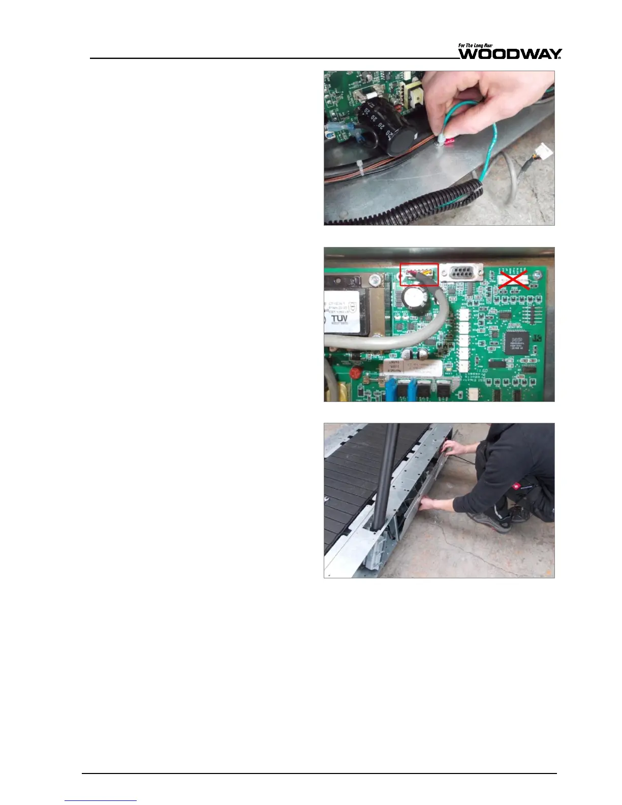
9. Attach the protective con-
ductor (green) to the con-
tact tab on the housing.
Fig. 45 Mercury/Path assembly, connection 3
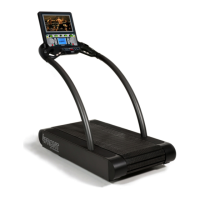
10. Connect the display cable
to the circuit board. The
connection is J10.
11. Connect and secure all oth-
er connections from hand-
rail.
Note:
Do not connect to
the position marked with
the red “X” in Fig. 31!
Fig. 46 Mercury/Path assembly, connection 4
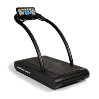
12. Reinstall electronic cover
plate on the right side of
the treadmill frame.
Fig. 47 Mercury/Path Assembly, electronic cover plate