January 2016
4-17
WorkCentre WorkCentre 4150/4250/4260WorkCentre 4150/4250/42604150/
REP 2.1
Repairs and Adjustments
REP 2.1 User Interface Assembly (4150)
Parts List on PL 2.10
Removal
NOTE: This procedure should only be performed on the 4150. For the 4250/4260 procedure,
refer to the table of contents.
WARNING
Switch off the electricity to the machine. Disconnect the power cord from the customer
supply while performing tasks that do not need electricity. Electricity can cause death or
injury. Moving parts can cause injury.
WARNING
Take care during this procedure. Sharp edges may be present that can cause injury.
CAUTION
Before performing this procedure, refer to General Disassembly Precautions, GP 10.
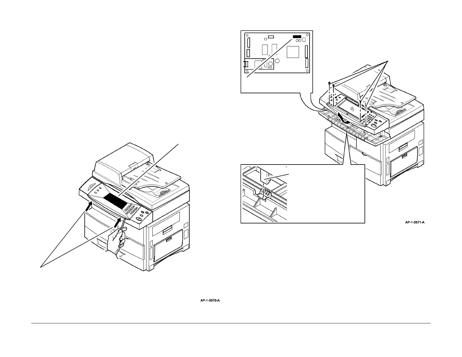
1. Remove the UI inlay, Figure 1.
NOTE: The UI inlay is secured by 4 clips. Two on each front corner.
Figure 1 UI inlay removal
2. Remove the UI assembly, Figure 2.
Figure 2 UI assembly removal
Replacement
1. Replacement is the reverse of the removal procedure.
2. If a new UI assembly has been installed, calibrate the touch screen. Refer to GP 12 User
Interface Tests Description.
1
Use a flat bladed screwdriver to carefully lift
both front corners of the UI inlay.
2
Carefully remove
the UI inlay.
2
Use a flat bladed screwdriver to
release the catch underneath
the UI assembly.
1
Remove 4 screws.
3
Disconnect CN6.
4
Remove the UI assembly.

 Loading...


