January 2016
4-186
WorkCentre WorkCentre 4150/4250/4260WorkCentre 4150/4250/42604150/
REP 14.3
Repairs and Adjustments
REP 14.3 Scanner Assembly (4250/4260/4265)
Parts List on PL 14.13, PL 14.16
Removal
NOTE: This procedure should only be performed on the 4250/4260 and 4265 machines. For
the 4150 procedure, refer to the table of contents.
WARNING
Switch off the electricity to the machine. Disconnect the power cord from the customer
supply while performing tasks that do not need electricity. Electricity can cause death or
injury. Moving parts can cause injury.
WARNING
Take care during this procedure. Sharp edges may be present that can cause injury.
CAUTION
Before performing this procedure, refer to General Disassembly Precautions, GP 10.
1. Remove the DADF. Refer to REP 5.3.
2. Remove the rear cover, PL 28.10 Item 6.
3. Disconnect CN1, CN2, CN3 and CN6 from the main PWB.
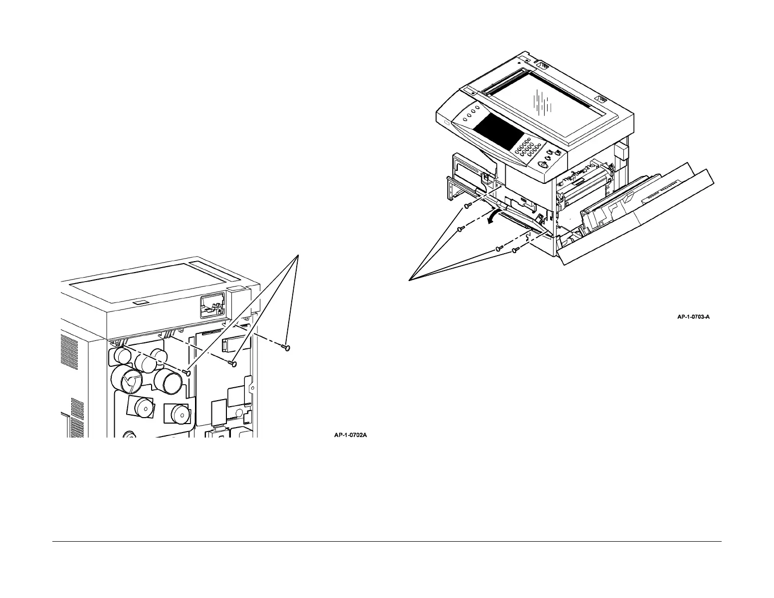
4. Remove the three Scanner mounting screws from the rear of the machine (Figure 1).
Figure 1 Removing the Scanner Assembly Mounting Screws
5. Open the side cover assembly, PL 7.30 Item 1, then the front door assembly, PL 28.10
Item 2.
6. Remove the toner cartridge, PL 9.10 Item 2 then the xerographic module, PL 9.10 Item 1.
7. Remove paper tray 1.
8. Remove the exit tray assembly, PL 28.10 Item 1 or the finisher, REP 12.1.
9. Remove the paper exit cover, PL 28.10 Item 4.
10. Remove the front door assembly (Figure 2).
Figure 2 Removing the Front Door Assembly
1
Remove the three
mounting screws.
1
Remove 4 screws, then the front door
assembly.

 Loading...


