January 2016
4-138
WorkCentre 4150/4250/4260WorkCentre WorkCentre 4150/4250/42604150/
REP 8.6, REP 8.7
Repairs and Adjustments
Replacement
1. Replacement is the reverse of the removal procedure.
CAUTION
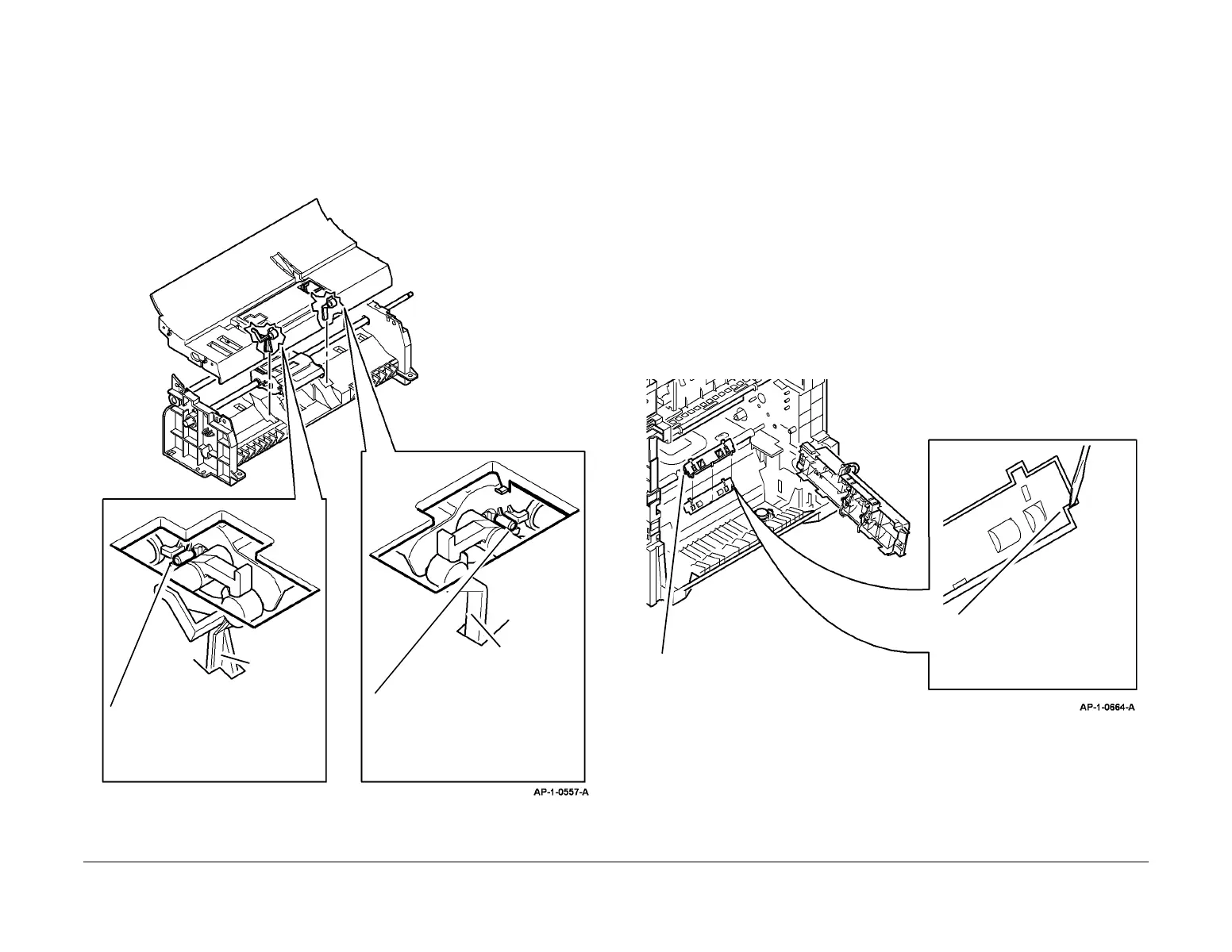
Do not damage the mylar guides positioned above the link arms. For clarity, the mylar guides
are not shown in Figure 4.
2. When the paper transport assembly is reassembled, ensure that the feed gates and link
arms are located correctly, Figure 4.
Figure 4 Feed Gate Position
REP 8.7 Transport Roll Idler Assembly
Parts List on PL 7.17
Removal
WARNING
Switch off the electricity to the machine. Disconnect the power cord from the customer
supply while performing tasks that do not need electricity. Electricity can cause death or
injury. Moving parts can cause injury.
WARNING
Take care during this procedure. Sharp edges may be present that can cause injury.
CAUTION
Before performing this procedure, refer to General Disassembly Precautions, GP 10.
1. Remove the paper transport assembly, REP 8.3.
CAUTION
The guide is secured by 5 clips. Take care when removing the guide. The clips are easily bro-
ken.
2. Remove the guide, Figure 1.
Figure 1 Guide Removal
3. Remove the transport roll idler assembly, PL 7.17 Item 5.
Replacement
Replacement is the reverse of the removal procedure.
Feed gate
in slot
1
Put the rear of the link arm below the
peg on the feed roll assembly.
2
Put the rear of the link arm below
the peg on the feed roll assembly.
Feed gate
in slot
1
Use a small, flat bladed screw-
driver to release the front and
rear of the guide. See CAUTION.
2
Remove the guide.

 Loading...


