January 2016
4-155
WorkCentre 4150/4250/4260WorkCentre WorkCentre 4150/4250/42604150/
REP 10.5, REP 10.6
Repairs and Adjustments
Replacement
CAUTION
Do not damage the fuser stripper fingers when reinstalling the heat roller assembly, refer to
Figure 3.
1. Replacement is the reverse of the removal procedure.
2. Ensure the locating tabs on the front heat roller collar are position in the recesses on the
heat roller, refer to Figure 3.
3. Ensure that the spring on the front jam lever is positioned in the slot on the fuser frame.
4. If a new heat roller assembly or pressure roller are installed, reset the HFSI count to zero.
Go to GP 16 High Frequency Service Items.
REP 10.6 Fuser Connector (4150)
Parts List on PL 4.15
Removal
NOTE: This procedure should only be performed on the 4150. For the 4250/4260 procedure,
refer to the table of contents.
WARNING
Switch off the electricity to the machine. Disconnect the power cord from the customer
supply while performing tasks that do not need electricity. Electricity can cause death or
injury. Moving parts can cause injury.
WARNING
Take care during this procedure. Sharp edges may be present that can cause injury.
CAUTION
Before performing this procedure, refer to General Disassembly Precautions, GP 10.
1. Remove the exit guide assembly, REP 10.2.
2. Remove the fuser connector retainer, PL 4.15 Item 21.
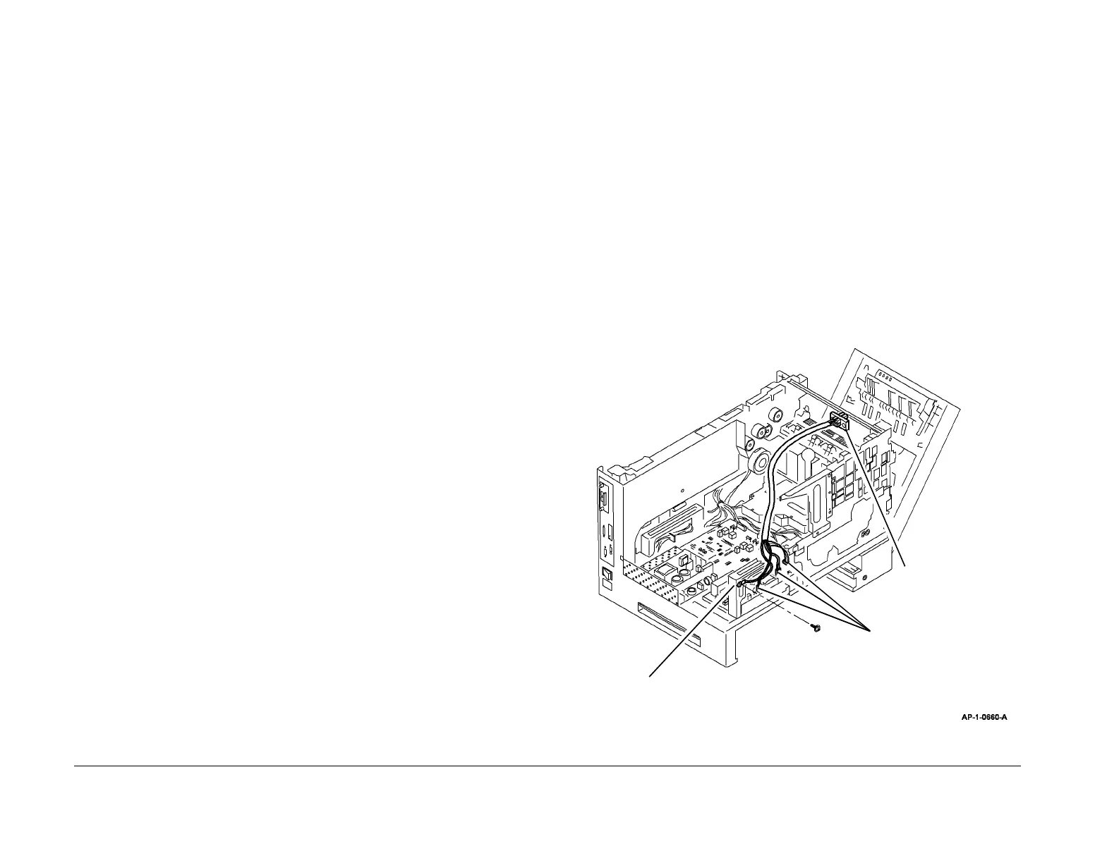
3. Remove the fuser connector, Figure 1.
Figure 1 Fuser connector
2
Disconnect CON3, CON8
and CON9 from power
supply unit 2.
1
Disconnect the ground
connector.
3
Remove the fuser
connector.

 Loading...


