January 2016
4-27
WorkCentre WorkCentre 4150/4250/4260WorkCentre 4150/4250/42604150/
REP 4.1
Repairs and Adjustments
REP 4.1 Main Drive Assembly (4150)
Parts List on PL 4.20
Removal
NOTE: This procedure should only be performed on the 4150. For the 4250/4260 procedure,
refer to the table of contents.
WARNING
Switch off the electricity to the machine. Disconnect the power cord from the customer
supply while performing tasks that do not need electricity. Electricity can cause death or
injury. Moving parts can cause injury.
WARNING
Take care during this procedure. Sharp edges may be present that can cause injury.
CAUTION
Before performing this procedure, refer to General Disassembly Precautions, GP 10.
1. Remove the rear cover, PL 28.10 Item 6.
2. Remove the toner cartridge, PL 9.10 Item 2 then the xerographic module, PL 9.10 Item 1.
3. Open the side cover assembly, PL 7.30 Item 1.
4. Remove the rear LSU fan duct, PL 6.10 Item 4.
CAUTION
Take care when the clutches are removed. The wiring to the clutches is thin and easily broken.
If necessary, carefully disconnect each clutch.
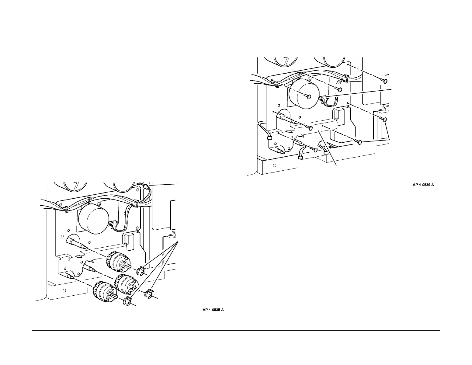
5. Prepare to remove the main drive assembly, Figure 1.
Figure 1 Preparation
6. Release all harnesses from the cable clamps on the main drive assembly.
7. Remove the main drive assembly, Figure 2.
NOTE: The position of each screw is numbered 1 to 7 on the main drive plate. Remove
the screws in reverse numerical order.
Figure 2 Main drive assembly removal
Replacement
1. Replacement is the reverse of the removal procedure.
2. The 7 screws that secure the main drive assembly must be installed in numerical order.
3. Ensure that the clutches are installed in the correct position, refer to Figure 3.
1
Disconnect the 2 pin
inline connector.
2
Remove 3 KL-clips.
3
Remove 3 clutches.
1
Disconnect CN1.
3
Carefully remove the main drive
assembly.
2
Remove 7 screws
(see NOTE).

 Loading...


