16 www.xilinx.com Spartan-6 FPGA PCB Design and Pin Planning
UG393 (v1.1) April 29, 2010
Chapter 2: Power Distribution System
Capacitor Specifications
The electrical characteristics of the capacitors in Table 2-1 are described in this section.
Characteristics of the PCB bulk and high-frequency capacitors are specified in Table 2-2,
followed by guidelines on acceptable substitutions. The equivalent series resistance (ESR)
ranges specified for these capacitors can be over-ridden. However, this requires analysis of
the resulting power distribution system impedance to ensure that no resonant impedance
spikes result.
PCB Bulk Capacitors
The purpose of the bulk capacitors is to cover the low-frequency range between where the
voltage regulator stops working (~100 KHz) and where the high-frequency capacitors start
working (~2 MHz). As specified in Table 2-1, all FPGA supplies require bulk capacitors.
The bulk capacitors in Table 2-1 and Table 2-2 are not necessarily in addition to the voltage
regulator output capacitors required by the regulator manufacturer, provided there is no
inductor, ferrite bead, choke, or other filter between the FPGA and the bulk capacitors.
However, if the FPGA bulk and regulator output requirements are merged, the total
capacitance of this network must not be less than the total bulk specified in Table 2-1 and
Table 2-2, and must comply with the regulator manufacturer’s output capacitor
requirements.
The bulk PCB capacitors specified in Table 2-1 are ceramic capacitors from Murata, a
capacitor manufacturer. This capacitor was selected for its value, size, and low-cost. It is
also RoHS compliant. If another manufacturer’s capacitors or another type of capacitor
(e.g., tantalum or high-performance electrolytic) meet the specifications listed in Table 2-2,
substitution is acceptable.
PCB High-Frequency Capacitors
There are two high-frequency capacitor values in Table 2-2: the 4.7 µF capacitor in an 0805
package and the 0.47 µF capacitor in an 0402 or 0204 package. Substitutions can be made
for some characteristics, but not others; see the notes attached to Table 2-2 for details.
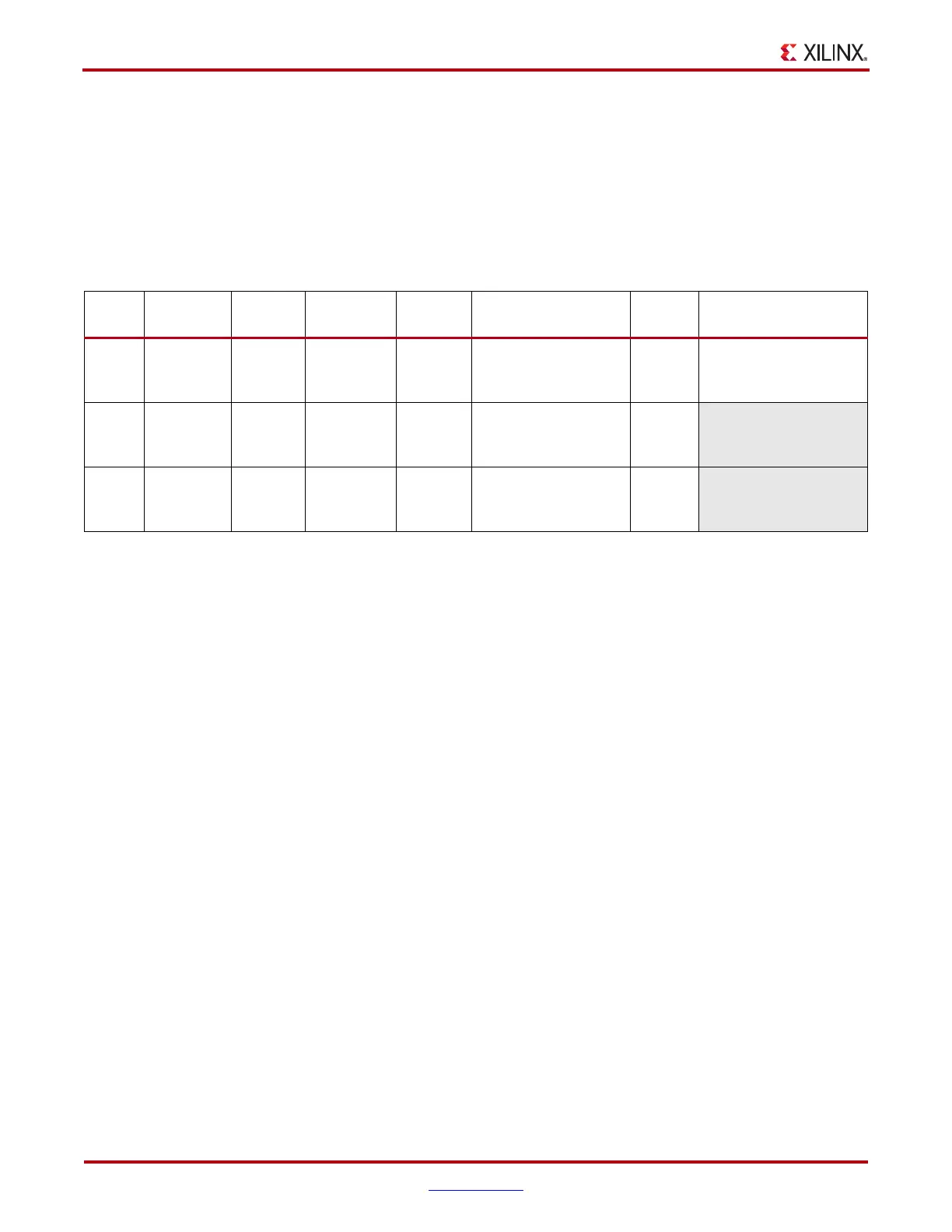
Table 2-2: PCB Capacitor Specifications
Ideal
Value
Value
Range
(1)
Body
Size
(2)
Type
ESL
Maximum
ESR Range
(3)
Voltage
Rating
(4)
Suggested
Part Number
100 µF C > 100 µF 1210
2-Terminal
Ceramic
X7R or X5R
5nH 10mΩ <ESR<60mΩ 6.3V GRM32ER60J107ME20L
4.7 µF C > 4.7 µF 0805
2-Terminal
Ceramic
X7R or X5R
2nH 10mΩ <ESR<60mΩ 6.3V
0.47 µF C > 0.47 µF
0204 or
0402
2-Terminal
Ceramic
X7R or X5R
1.5 nH 10 mΩ <ESR<60mΩ 6.3V
PCB Capacitor Substitution Rules:
1. Values can be larger than specified.
2. Body size can be smaller than specified.
3. ESR must be within the specified range.
4. Voltage rating can be higher than specified.

 Loading...


