32 www.xilinx.com Spartan-6 FPGA PCB Design and Pin Planning
UG393 (v1.1) April 29, 2010
Chapter 2: Power Distribution System
Unconnected V
CCO
Pins
In some cases, one or more I/O banks in an FPGA are not used (for example, when an
FPGA has far more I/O pins than the design requires). In these cases, it might be desirable
to leave the bank’s associated V
CCO
pins unconnected, as it can free up some PCB layout
constraints (less voiding of power and ground planes from via antipads, less obstacles to
signals entering and exiting the pinout array, more copper area available for other
planelets in the otherwise used plane layer).
Leaving the V
CCO
pins of unused I/O banks floating reduces the level of ESD protection
on these pins and the I/O pins in the bank. ESD events at the unconnected solder balls in
the inner rows of a BGA pinout array are unlikely and not considered a high risk.
However, ESD events at exposed pins on the perimeter of a QFP-type package are likely.
In these packages, the V
CCO
pins of unused I/O banks should be connected to the V
CCO
of
a neighboring I/O bank.
Simulation Methods
Simulation methods, ranging from very simple to very complex, exist to predict the PDS
characteristics. An accurate simulation result is difficult to achieve without using a fairly
sophisticated simulator and taking a significant amount of time.
Basic lumped RLC simulation is one of the simplest simulation methods. Though it does
not account for the distributed behavior of a PDS, it is a useful tool for selecting and
verifying that combinations of decoupling capacitor values will not lead to large anti-
resonances.
Lumped RLC simulation is performed either in a version of SPICE or other circuit
simulator, or by using a mathematical tool like MathCAD or Microsoft Excel. Istvan Novak
publishes a free Excel spreadsheet for lumped RLC impedance calculation (among other
useful tools for PDS simulation) on his website:
http://www.electrical-integrity.com
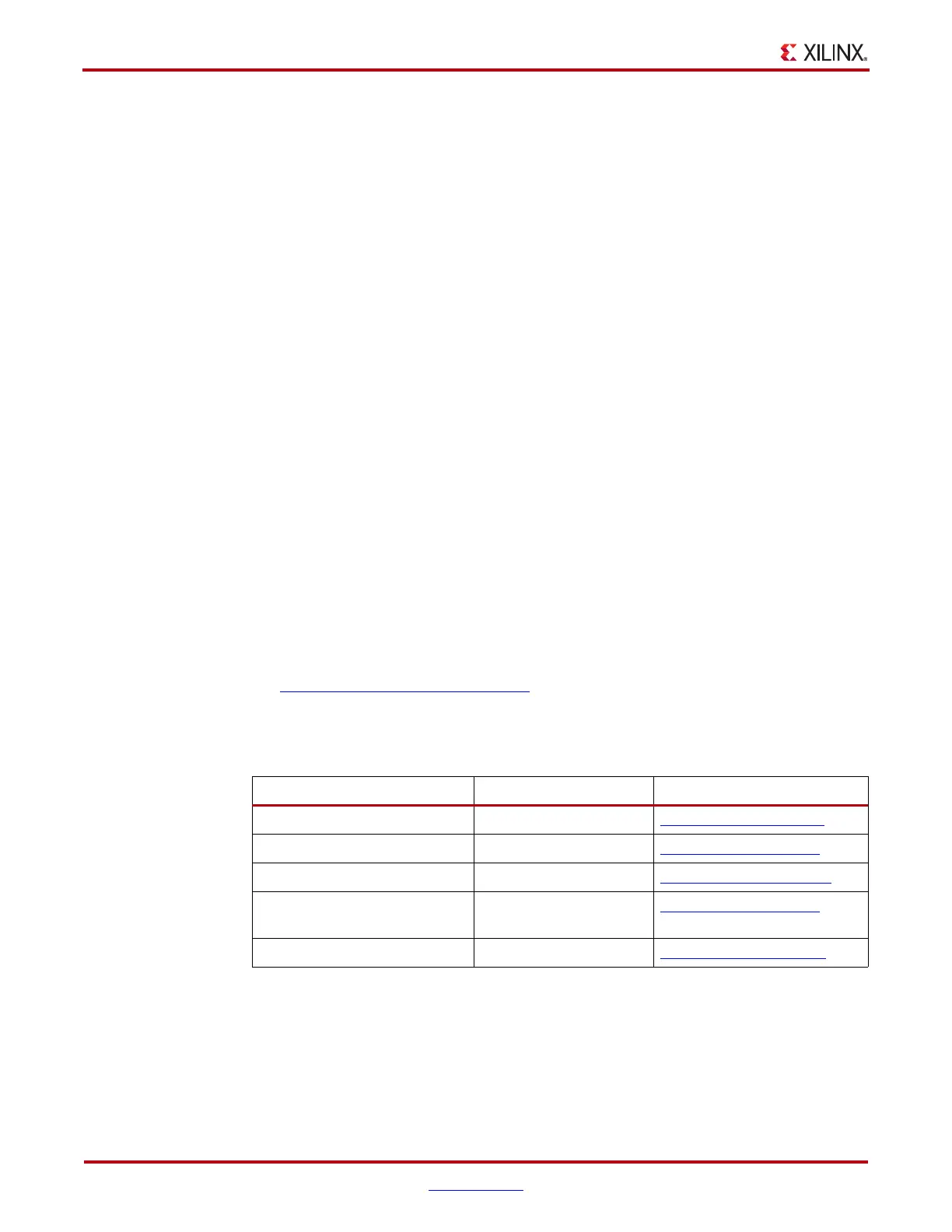
Table 2-4 also lists a few EDA tool vendors for PDS design and simulation. These tools
span a wide range of sophistication levels.
Table 2-4: EDA Tools for PDS Design and Simulation
Tool Vendor Website URL
ADS Agilent http://www.agilent.com
SIwave, HFSS Ansoft http://www.ansoft.com
Specctraquest Power Integrity Cadence http://www.cadence.com
Speed 2000, PowerSI, PowerDC,
OptimizePI
Sigrity http://www.sigrity.com
Hyperlynx PI Mentor http://www.mentor.com

 Loading...


