6C13G11
6-20
1
2
3
4
5
6
7
8
9
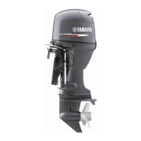
2. Align the center of the set pin
a
with the
alignment mark
b
on the bracket.
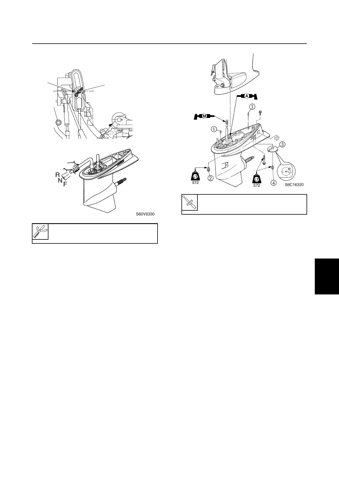
3. Install the two dowels
1
into the lower
unit.
4. Install the lower unit into the upper case,
and then tighten the lower case mounting
bolts
2
to the specified torque.
5. Install the trim tab
3
to its original posi-
tion, and then tighten the trim tab bolt
4
.
Shift rod push arm: 90890-06052
S6C16310
b
a
Lower case mounting bolt
2
:
39 N·m (3.9 kgf·m, 28.8 ft·lb)
Drive shaft and lower case (F50, F60)
 Loading...