Meters
Reference Manual
115
For INPUT METER
Fader color
The channel color is the same as the currently selected MIX/MATRIX bus (SEND MASTER).
The position of the fader is the level of the signal sent to the bus.
The fader turns gray if you switch the SEND button to OFF or switch the channel OFF.
For OUTPUT METER
Only the fader for the signal sent from the MIX bus to the MATRIX bus changes color.
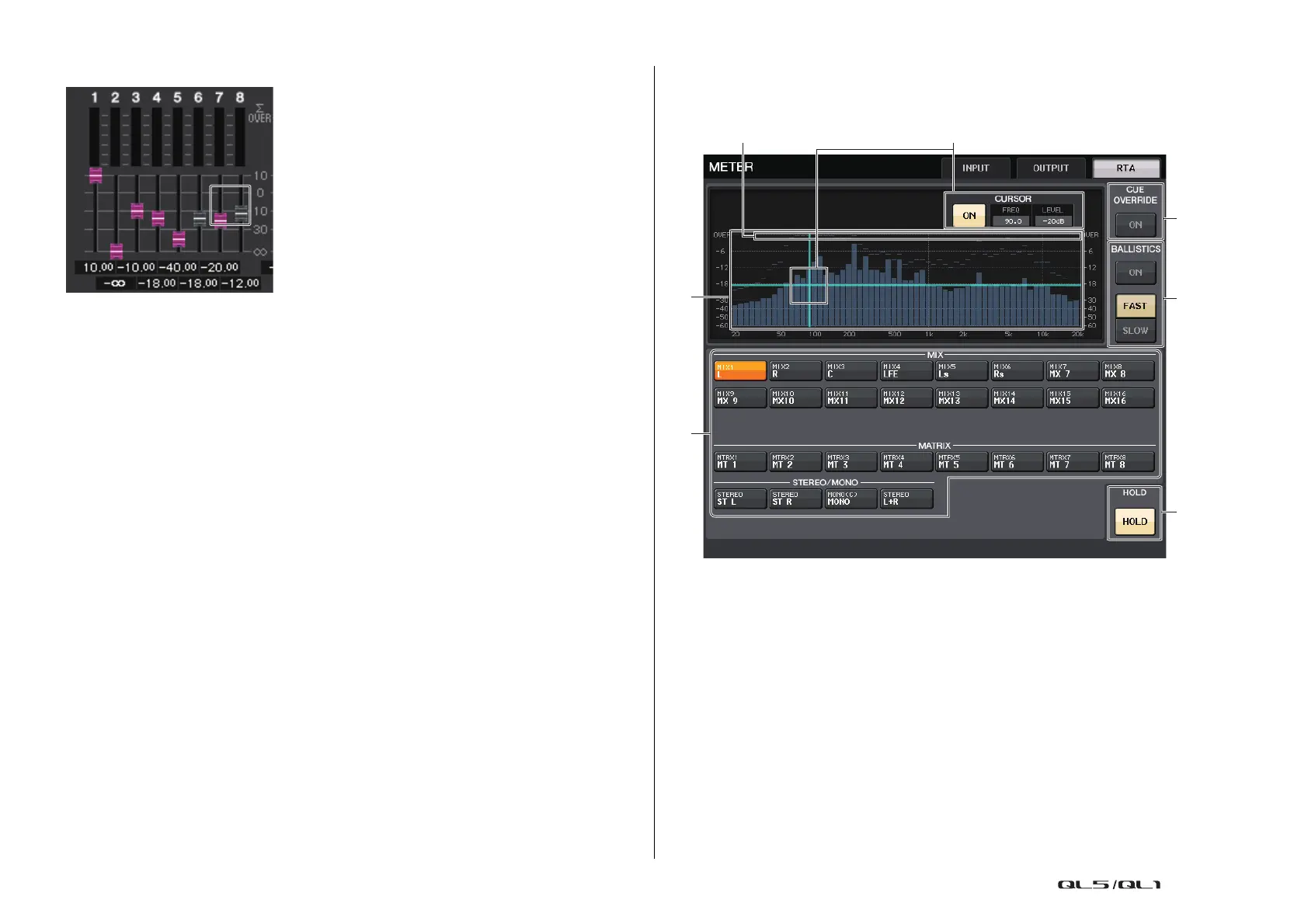
RTA METER screen
This is the real time analyzer screen. The results of a frequency analysis for the selected
source are shown in the 1/6 octave band (61 band).
1 Frequency Response graph
A graph of a frequency analysis is shown in the 1/6 octave band.
2 Source selection buttons
Use these buttons to specify the output channel whose frequency response you want to
see.
3 OVER display
Data that exceeds 0dB is shown the same as the OVER indicator.
4 Cross-hair cursor display
The frequency and level at the point you touch on the graph are displayed.
 Loading...


