COOLING SYSTEM DIAGRAMS
SPEC 0*
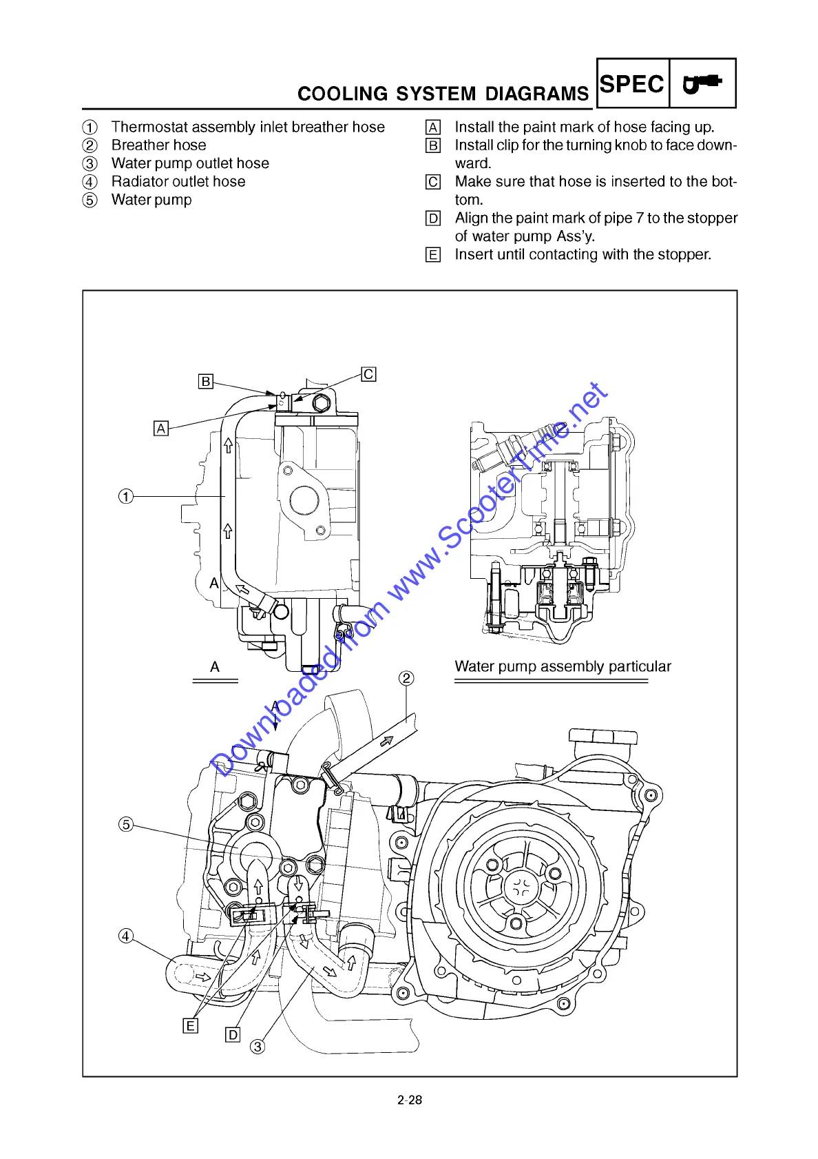
1 Thermostat assembly inlet breather hose
2 Breather hose
3 Water pump outlet hose
4 Radiator outlet hose
5 Water pump
A Install the paint mark of hose facing up.
B Install clip for the turning knob to face down-
ward.
C Make sure that hose is inserted to the bot-
tom.
D Align the paint mark of pipe 7 to the stopper
of water pump Ass’y.
E Insert until contacting with the stopper.
2-28
Downloaded from www.ScooterTime.net
 Loading...