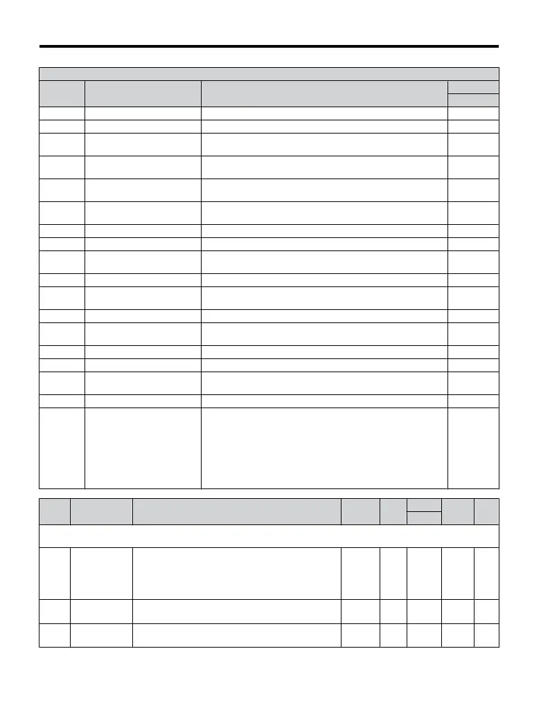
H2 Multi-Function Digital Output Settings
H2-01
Setting
Function Description
Mode
V/f
0 During Run Closed: A Run command is active or voltage is output O
1 Zero Speed Closed: Output frequency is 0 O
2 Speed Agree 1
Closed: Output frequency equals the speed reference (plus or
minus 2 Hz)
O
4 Frequency Detection 1
Closed: Output frequency is less than or equal to the value in
L4-01 plus 2 Hz
O
5 Frequency Detection 2
Closed: Output frequency is greater than the value in L4-01plus
2 Hz
O
6 Drive Ready
Closed: Drive Ready. The drive is powered up, not in a fault
state, and in the Drive mode
O
7 DC Bus Undervoltage Closed: DC bus voltage is below the Uv trip level set in L2-05 O
8 During Baseblock (N.O.) Closed: There is no output voltage O
B Torque Detection 1 (N.O.)
Closed: Output current/torque exceeds the torque value set in
parameter L6-02 for longer than the time
set in parameter L6-03
O
E Fault Closed: Fault occurred (other than CPF00 and CPF01) O
F Not used
Set this value when the terminal is not used, or when using the
terminal in the pass-through mode
O
10 Minor Fault Closed: An alarm is triggered O
17 Torque Detection 1 (N.C.)
Open: When the output current/torque exceeds the value set in
parameter L6-02 for more time than is set in parameter L6-03
O
1A Reverse Direction Closed: Drive is running in the reverse direction O
1E Restart Enabled Closed: An automatic restart is performed O
3C LOCAL/REMOTE Status
Closed: LOCAL
Open: REMOTE
O
3D Speed Search Closed: Speed search is being executed O
100 to
102;
104 to
108;
10B, 10E,
110, 117,
11A, 11E,
13C, 13D
H2 Parameter Functions
Reversed Output Switching
of 0 to 13D
Reverse the output switching of the multi-function output
functions. Set the last two digits of 1oo to reverse the output
signal of that specific function
Examples:
Setting “108” reverses the output of “During
baseblock”, which
is setting value 08
Setting “13C” reverses the output of “3CLOCAL/REMOTE
Status”, which is setting “3C”
O
No. Name Description Range Def.
Mode
Addr.
Hex
Pg.
V/f
H3: Analog Inputs
Use H3 parameters to set the analog input terminals.
H3-01
Terminal A1
Signal Level
Selection
Sets the input level for terminal A1.
0: 0 to +10 V (lower limit)
1: 0 to +10 V (no lower limit)
2: 4 to 20 mA
3: 0 to 20 mA
0 to 3 0 O 410 —
H3-03
<22>
Terminal A1
Gain Setting
Sets the level of the input value when 10 V is input at
terminal A1.
-999.9 to
999.9
100.0
%
O 411 —
H3-04
<22>
Terminal A1
Bias Setting
Sets the level of the input value when 0 V is input at
terminal A1.
-999.9 to
999.9
0.0% O 412 —
B.2 Parameter Table
208
YASKAWA ELECTRIC TOEP C710606 25B YASKAWA AC Drive J1000 Installation & Start-Up Manual
2/6/2008-14:44

 Loading...


