Standards Compliance
5
5.3 UL Standards
YASKAWA SIEPC71061753C GA500 Technical Manual 191
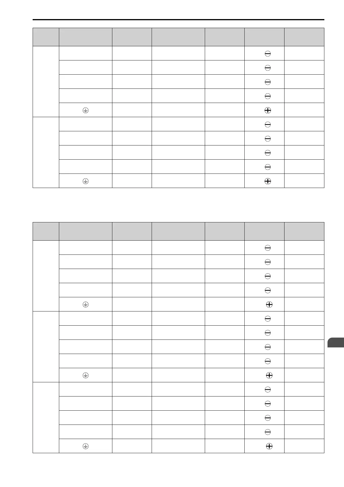
Model Terminal
Recomm. Gauge
AWG, kcmil
Applicable Gauge
AWG, kcmil
Wire Stripping
Length
*1
mm
Terminal Screw
Size and Shape
Tightening Torque
N∙m (lbf∙in)
B012
L/L1, N/L2 8 14 - 8 10
M4
1.5 - 1.7
(13.5 - 15)
U/T1, V/T2, W/T3 12 14 - 10 10
M4
1.5 - 1.7
(13.5 - 15)
-, +1 8 14 - 8 10
M4
1.5 - 1.7
(13.5 - 15)
B1, B2 14 14 - 12 10
M4
1.5 - 1.7
(13.5 - 15)
10
*2
14 - 10
*2
-
M4
1.2 - 1.5
(10.6 - 13.3)
B018
L/L1, N/L2 8 12 - 6 10
M4
1.5 - 1.7
(13.5 - 15)
U/T1, V/T2, W/T3 10 14 - 8 10
M4
1.5 - 1.7
(13.5 - 15)
-, +1 8 12 - 6 10
M4
1.5 - 1.7
(13.5 - 15)
B1, B2 14 14 - 12 10
M4
1.5 - 1.7
(13.5 - 15)
8
*2
12 - 8
*2
-
M5
2.0 - 2.5
(17.7 - 22.1)
*1 Remove insulation from the ends of wires to expose the length of wire shown.
*2 If you turn on the internal EMC filter, the leakage current of the drive will be more than 3.5 mA. Use the closed-loop crimp terminals
to connect a protective ground wire that has a minimum cross-sectional area of 10 mm
2
(copper wire).
Three-Phase 200 V Class
Model Terminal
Recomm. Gauge
AWG, kcmil
Applicable Gauge
AWG, kcmil
Wire Stripping
Length
*1
mm
Terminal Screw
Size and Shape
Tightening Torque
N∙m (lbf∙in)
2001
R/L1, S/L2, T/L3 14 14 6.5
M3
0.5 - 0.6
(4.4 - 5.3)
U/T1, V/T2, W/T3 14 14 6.5
M3
0.5 - 0.6
(4.4 - 5.3)
-, +1, +2 14 14 6.5
M3
0.5 - 0.6
(4.4 - 5.3)
B1, B2 14 14 6.5
M3
0.5 - 0.6
(4.4 - 5.3)
14
*2
14
*2
-
M3.5
0.8 - 1.0
(7.1 - 8.9)
2002
R/L1, S/L2, T/L3 14 14 6.5
M3
0.5 - 0.6
(4.4 - 5.3)
U/T1, V/T2, W/T3 14 14 6.5
M3
0.5 - 0.6
(4.4 - 5.3)
-, +1, +2 14 14 6.5
M3
0.5 - 0.6
(4.4 - 5.3)
B1, B2 14 14 6.5
M3
0.5 - 0.6
(4.4 - 5.3)
14
*2
14
*2
-
M3.5
0.8 - 1.0
(7.1 - 8.9)
2004
R/L1, S/L2, T/L3 14 14 6.5
M3
0.5 - 0.6
(4.4 - 5.3)
U/T1, V/T2, W/T3 14 14 6.5
M3
0.5 - 0.6
(4.4 - 5.3)
-, +1, +2 14 14 6.5
M3
0.5 - 0.6
(4.4 - 5.3)
B1, B2 14 14 6.5
M3
0.5 - 0.6
(4.4 - 5.3)
14
*2
14
*2
-
M3.5
0.8 - 1.0
(7.1 - 8.9)

 Loading...


