Parameter Details
12
12.3 b: Application
YASKAWA SIEPC71061753C GA500 Technical Manual 503
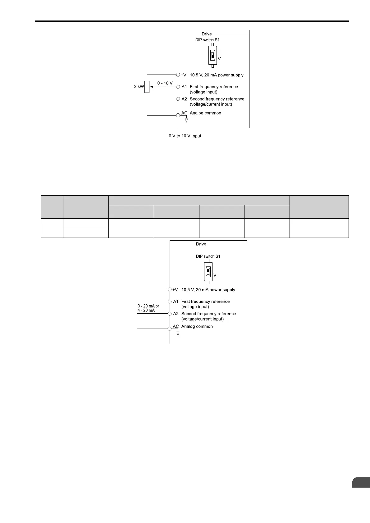
Figure 12.7 Example of Setting the Frequency Reference with a Voltage Signal to Terminal A1
Note:
You can also use this diagram to wire terminal A2.
• Current Input
Refer to Table 12.24 to use a current signal input to one of the MFAI terminals.
Table 12.24 Frequency Reference Current Input
Terminal Signal Level
Parameter Settings
Note
Signal Level
Selection
Function Selection Gain Bias
A2 4 - 20 mA H3-09 = 2 H3-10 = 0
[Frequency Reference]
H3-11 H3-12 Set DIP switch S1 to “I” for
current input.
0 - 20 mA H3-09 = 3
Figure 12.8 Example of Setting the Frequency Reference with a Current Signal to Terminal A2
Changing between Master and Auxiliary Frequency References
Use the multi-step speed reference function to change the frequency reference input between terminals A1 and
A2.
2 : Memobus/Modbus Communications
Use MEMOBUS/Modbus communications to enter the frequency reference.
3 : Option PCB
Use a communications option connected to the drive to enter the Run command.
Refer to the instruction manual included with the option to install and set the option.
Note:
If b1-01 = 3 but you did not connect an option, oPE05 [Run Cmd/Freq Ref Source Sel Err] will flash on the keypad.
4 : Pulse Train Input
Use a pulse train signal from the pulse train input terminal RP to enter the frequency reference.
Do this procedure to make sure that the pulse train signal is operating correctly.
1. Set b1-01 = 4, H6-01 = 0 [Terminal RP Pulse Train Function = Frequency Reference].

 Loading...


