3.3 Main Circuit Wiring
82 YASKAWA SIEPC71061753C GA500 Technical Manual
Use the values in Table 3.3 to adjust the drive carrier frequency. For systems that have 100 m (328 ft) or longer
motor wiring, if you use metal conduits or isolated cables for each phase, it will increase stray capacitance.
Table 3.3 Carrier Frequency against Cable Length Between Drive and Motor
Wiring Distance Between the Drive
and Motor
50 m (164 ft) Maximum 100 m (328 ft) Maximum More than 100 m (328 ft)
Carrier Frequency 15 kHz or less 5 kHz or less 2 kHz or less
Note:
• To set the carrier frequency in a drive that is operating more than one motor, calculate the cable length as the total distance of wiring to
all connected motors.
• If the length of the wire between the drive and an induction motor is longer than 100 m (328 ft), set A1-02 = 0[V/f].
• The maximum cable length between the drive and a PM motor is 100 m (328 ft).
• If the cable length between the drive and the motor is too long when A1-02 = 6 [AOLV/PM] or 8 [EZOLV], change the setting to A1-02
= 5 [OLV/PM].
• When you connect to a PM motor, it can be necessary to adjust the overcurrent detection. Refer to L8-27: Overcurrent Detection Gain
on page 732 for more information.
■ Ground Wiring
Follow the precautions to wire the ground for one drive or a series of drives.
WARNING! Electrical Shock Hazard. Make sure that the protective ground wire complies with technical standards and local
safety regulations. The EN 61800-5-1:2007 standard specifies that you must wire the power supply to automatically de-energize
when the protective ground wire disconnects. If you turn on the internal EMC filter, the leakage current of the drive will be more
than 3.5 mA. Use the closed-loop crimp terminal to connect a protective ground wire that has a minimum cross-sectional area of
10 mm
2
(copper wire). If you do not obey the standards and regulations, it can cause serious injury or death.
WARNING! Electrical Shock Hazard. Ground the neutral point on the power supply of drive models BxxxE, 2xxxE, and 4xxxE to
comply with the EMC Directive before you turn on the EMC filter or if there is high resistance grounding. If you turn ON the EMC
filter, but you do not ground the neutral point, it can cause serious injury or death.
WARNING! Electrical Shock Hazard. Use a ground wire that complies with technical standards on electrical equipment and use
the minimum length of ground wire. Incorrect equipment grounding can cause serious injury or death from dangerous electrical
potentials on the equipment chassis.
WARNING! Electrical Shock Hazard.
Correctly ground the ground terminals. Obey federal and local electrical wiring codes for correct grounding methods. The
maximum grounding resistance is
• 200 V class: ground to 100 Ω or less
• 400 V class: ground to 10 Ω or less
If you touch electrical equipment that is not grounded, it can cause serious injury or death.
Note:
• Only use the drive grounding wire to ground the drive. Do not share the ground wire with other devices such as welding machines or
large-current electrical equipment. Incorrect equipment grounding can cause drive or equipment malfunction from electrical
interference.
• To connect more than one drive to the same grounding circuit, follow the instructions in the instruction manual. Incorrect equipment
grounding can cause drive or equipment malfunction from electrical interference.
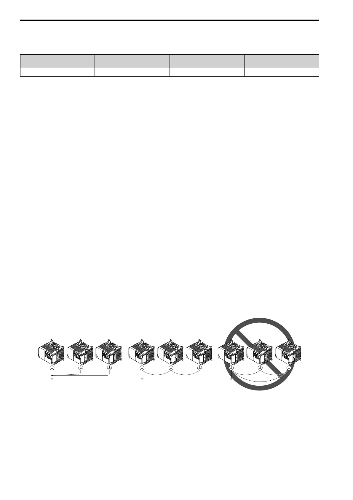
When you connect more than one drive, refer to Figure 3.24. Do not loop the grounding wire.
Figure 3.24 Wiring More than One Drive
■ Wiring the Main Circuit Terminal Block
WARNING! Electrical Shock Hazard. Before you wire the main circuit terminals, make sure that MCCB and MC are OFF. If you
touch electrical equipment when MCCB and MC are ON, it can cause serious injury or death.
■ Main Circuit Configuration
The figures in this section show the different schematics of the drive main circuit. The connections change when
the drive capacity changes. The DC power supply for the main circuit also supplies power to the control circuit.
 Loading...


