Electrical Installation
3
3.5 Control Circuit Wiring
YASKAWA SIEPC71061753C GA500 Technical Manual 93
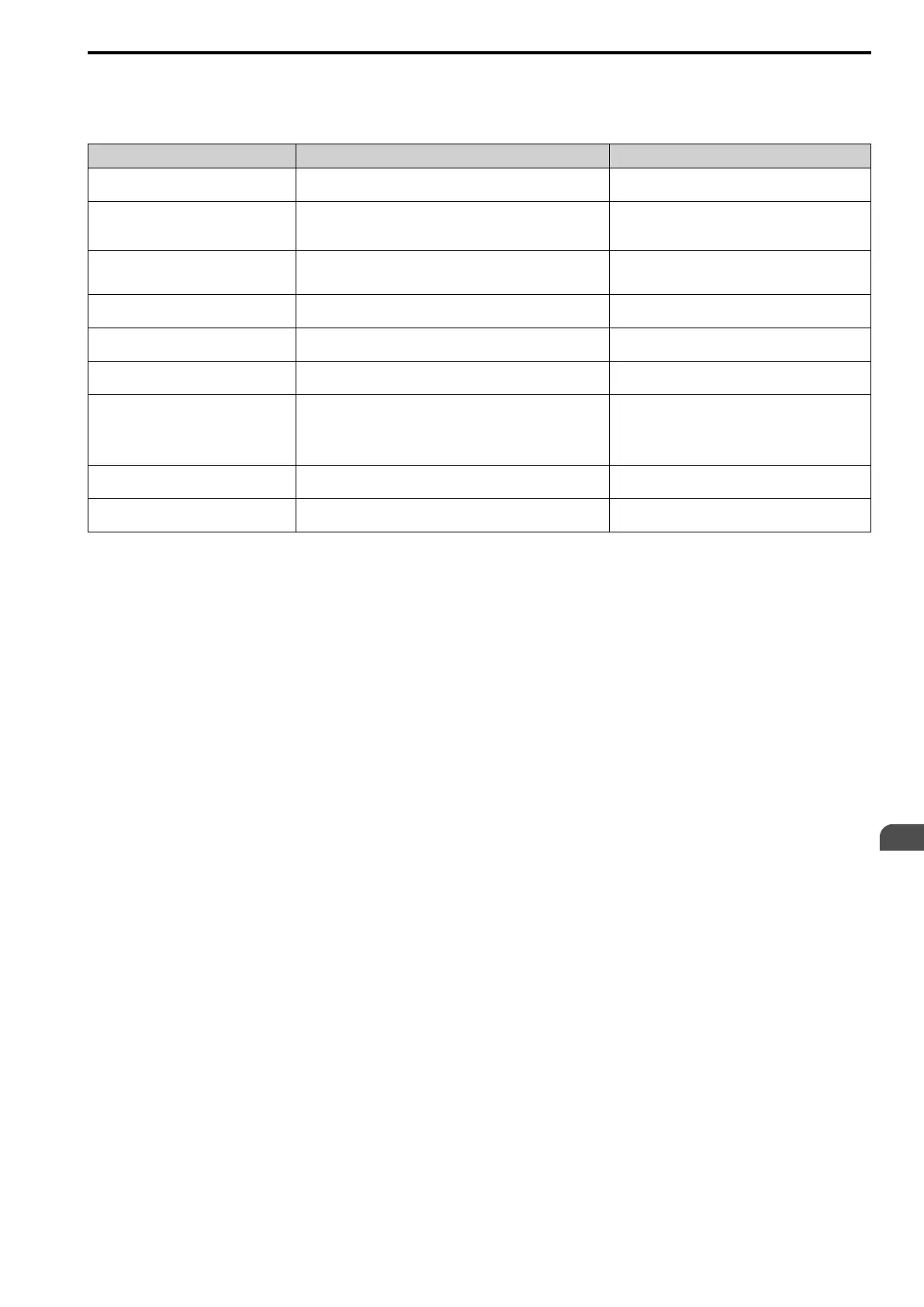
Operation When Using External 24 V Power Supply
To operate the drive, de-energize the main circuit power supply and connect an external 24 V power supply to
terminals PS-AC.
Function Operation Solution
Keypad The keypad operates the same as when the main circuit power supply
is ON. The drive will not detect oPr [Keypad Connection Fault].
-
Data Log The data log function operates the same as when the main circuit
power supply is ON.
The operation is different for different drive software versions.
*1
-
Communications by Communication Option
or MEMOBUS/Modbus Communication
Terminals
Communication operates the same as when the main circuit power
supply is ON. -
MFAI MFAI operates the same as when the main circuit power supply is
ON.
-
MFAO MFAO operates the same as when the main circuit power supply is
ON.
-
MFDI MFDI does not operate when the main circuit power supply of the
drive is OFF.
Connect the external 24 V power supply to MFDI
selection common terminal (SC).
*2
MFDO
Multi-Function Photocoupler Output
Fault Relay Output Terminal
MFDO operates the same as when the main circuit power supply is
ON.
The operations of MFDO terminals and fault relay output terminals
set for H2-xx = E, 10E [Fault] are different for different drive
software versions.
*3
-
Pulse Train Input Pulse train input operates the same as when the main circuit power
supply is ON.
-
Pulse train output Pulse train output operates the same as when the main circuit power
supply is ON.
-
*1 When you use an external 24 V power supply, the operation of the data log function is different for different drive software versions.
On drives with software versions PRG: 01015 and later, you can continue the data log function.
Note:
The “PRG” column on the nameplate on the right side of the drive identifies the software version. You can also use U1-25
[SoftwareNumber FLASH] to identify the software version.
*2 When you use MFDI and a Digital Input option (DI-A3), wire the terminals as shown in Wiring MFDI Terminals on page 93.
*3 When you use an external 24 V power supply, the operation of the MFDO terminals are different for different drive software
versions.
Note:
The “PRG” column on the nameplate on the right side of the drive identifies the software version. You can also use U1-25
[SoftwareNumber FLASH] to identify the software version.
• Drive software versions PRG: 01013 and later
When the main circuit power supply of the drive turns off, and you remove the cause of a fault and do a fault reset from the
keypad, the fault relay output terminals and the MFDO terminals set for H2-xx = E, 10E [Fault] will change status.
• Drive software versions PRG: 01012 and earlier
When the main circuit power supply of the drive turns off, remove the cause of a fault and do a fault reset from the keypad. The
fault relay output terminals and the MFDO terminals set for H2-xx = E, 10E [Fault] will keep the same status as before the main
circuit power supply of the drive turned off. The fault code shown on the keypad will disappear.
Wiring MFDI Terminals
If you de-energize the main circuit power supply, the MFDI terminals will not operate, even when you connect an
external 24 V power supply to terminals PS-AC. When you set N.O. functions to H1-xx [MFDI Function Select],
MFDI terminals always de-activate. When you set N.C. functions, MFDI terminals always activate. Connect the
external 24 V power supply to the MFDI selection common terminal (SC). Refer to Figure 3.38 for more
information.

 Loading...


