2.2 Monitors
2.2.2 Interpreting the Monitor Displays
2-11
2
Parameter/Monitor Functions
Σ-7W MECHATROLINK-III Communications Reference
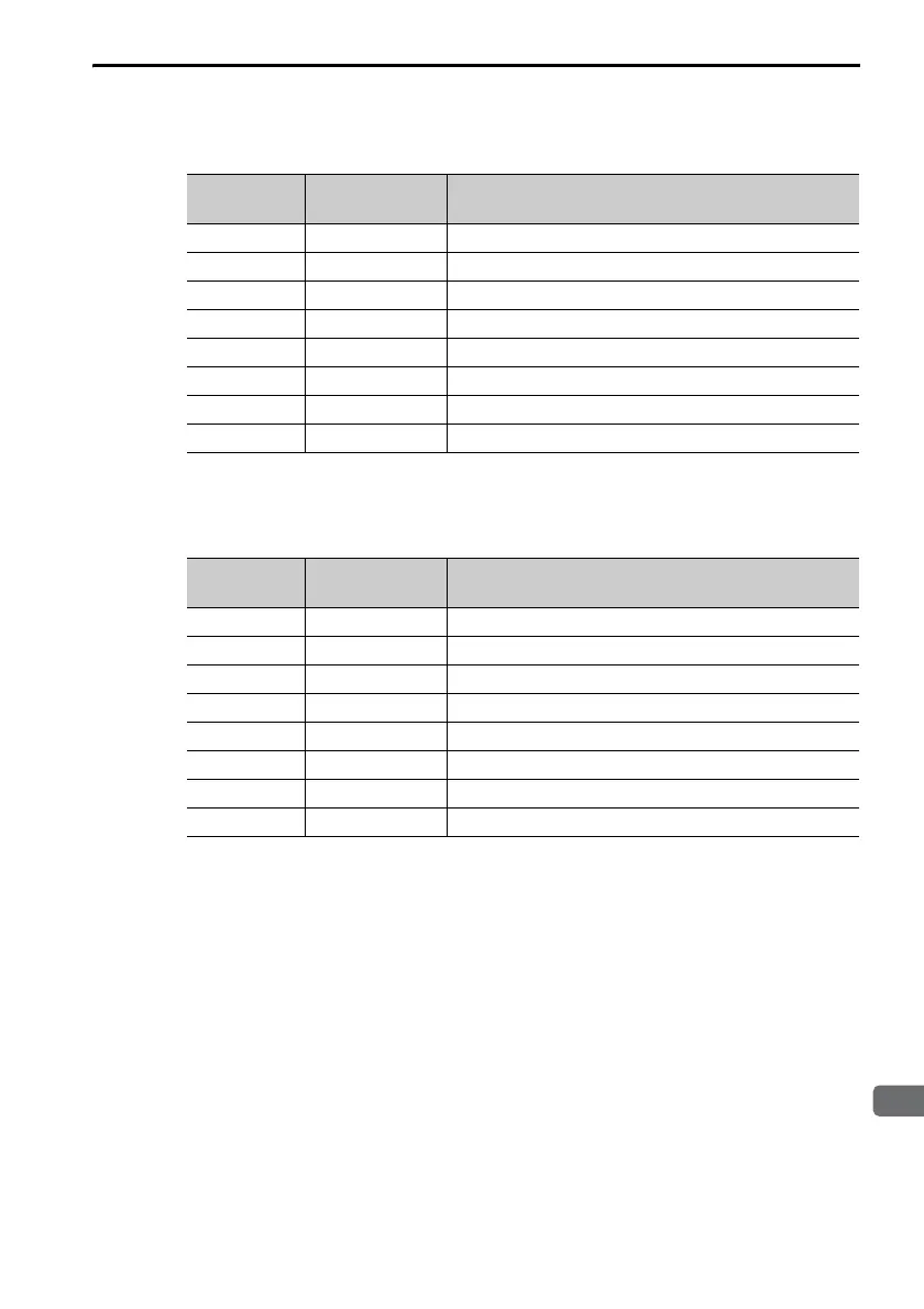
SERVOPACKs When Axis 1 Is Displayed
* The default settings are given.
Σ-7W MECHATROLINK-III Communications Reference
SERVOPACKs When Axis 2 Is Displayed
* The default settings are given.
Display Digit
Number
Input Pin
Number
Signal Name*
(You can change the allocations.)
1 CN1-3 P-OT (Forward Drive Prohibit) signal
2 CN1-4 N-OT (Reverse Drive Prohibit) signal
3 CN1-5 /DEC (Origin Return Deceleration Switch) signal
4 CN1-6 /EXT1 (External Latch Input 1) signal
5 CN1-7 /EXT2 (External Latch Input 2) signal
6 CN1-8 /EXT3 (External Latch Input 3) signal
7 –Reserved.
8 –Reserved.
Display Digit
Number
Input Pin
Number
Signal Name*
(You can change the allocations.)
1 CN1-9 P-OT (Forward Drive Prohibit) signal
2 CN1-10 N-OT (Reverse Drive Prohibit) signal
3 CN1-11 /DEC (Origin Return Deceleration Switch) signal
4 CN1-12 /EXT1 (External Latch Input 1) signal
5 CN1-13 /EXT2 (External Latch Input 2) signal
6 CN1-14 /EXT3 (External Latch Input 3) signal
7 –Reserved.
8 –Reserved.

 Loading...


