2.2 Monitors
2.2.2 Interpreting the Monitor Displays
2-10
2.2.2
Interpreting the Monitor Displays
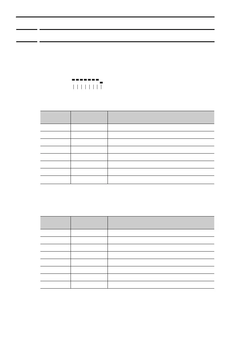
Input Signal Monitor
The input signal monitor (Un005) is displayed as shown below. The top
indicates OFF (high level) and the bottom indicates ON (low level).
Undefined digits are always shown as being ON.
Σ-7S Analog Voltage/Pulse Train Reference SERVOPACKs
*1. The default settings are given.
*2. You cannot change the allocation.
Σ-7S MECHATROLINK-II or MECHATROLINK-III Communi-
cations Reference SERVOPACKs
* The default settings are given.
Display Digit
Number
Input Pin
Number
Signal Name
*1
(You can change the allocations.)
1 CN1-40 /S-ON (Servo ON) signal
2 CN1-41 /P-CON (Proportional Control) signal
3 CN1-42 P-OT (Forward Drive Prohibit) signal
4 CN1-43 N-OT (Reverse Drive Prohibit) signal
5 CN1-44 /ALM-RST (Alarm Reset) signal
6 CN1-45 /P-CL (Forward External Torque Limit) signal
7 CN1-46 /N-CL (Reverse External Torque Limit) signal
8 CN1-4
SEN (Absolute Data Request) signal
*2
Display Digit
Number
Input Pin
Number
Signal Name*
(You can change the allocations.)
1 CN1-13 /SI0 (General-purpose Sequence Input 0) signal
2 CN1-7 P-OT (Forward Drive Prohibit) signal
3 CN1-8 N-OT (Reverse Drive Prohibit) signal
4 CN1-9 /DEC (Origin Return Deceleration Switch) signal
5 CN1-10 /EXT1 (External Latch Input 1) signal
6 CN1-11 /EXT2 (External Latch Input 2) signal
7 CN1-12 /EXT3 (External Latch Input 3) signal
8 – Reserved.
Un005=
876543 2 1 Digit

 Loading...


