2.2 Monitors
2.2.2 Interpreting the Monitor Displays
2-12
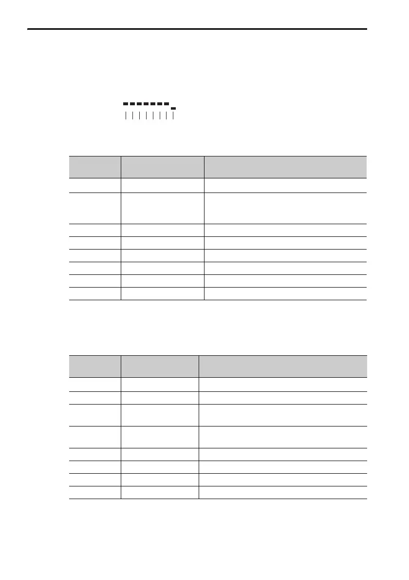
Output Signal Monitor
The output signal monitor (Un006) is displayed as shown below. The top
indicates OFF (high level) and the bottom indicates ON (low level). Unde-
fined digits are always shown as being ON.
Σ-7S Analog Voltage/Pulse Train Reference SERVOPACKs
*1. The default settings are given.
*2. You cannot change the allocation.
Σ-7S MECHATROLINK-II or MECHATROLINK-III Communi-
cations Reference SERVOPACKs
*1. The default settings are given.
*2. You cannot change the allocation.
Display Digit
Number
Output Pin
Number
Signal Name
*1
(You can change the allocations.)
1 CN1-31 and CN1-32
ALM (Servo Alarm) signal
*2
2 CN1-25 and CN1-26
/COIN (Positioning Completion) signal or
/V-CMP (Speed Coincidence Detection)
signal
3 CN1-27 and CN1-28 /TGON (Rotation Detection Output) signal
4 CN1-29 and CN1-30 /S-RDY (Servo Ready) signal
5 CN1-37 ALO1 (Alarm Code Output) signal
6 CN1-38 ALO2 (Alarm Code Output) signal
7 CN1-39 ALO3 (Alarm Code Output) signal
8 ––
Display Digit
Number
Input Pin
Number
Signal Name
*1
(You can change the allocations.)
1 CN1-3 and CN1-4
ALM (Servo Alarm) signal
*2
2 CN1-1 and CN1-2 /BK (Brake) signal
3
CN1-23 and
CN1-24
/SO2 (General-purpose Sequence Output 2)
signal
4
CN1-25 and
CN1-26
/SO3 (General-purpose Sequence Output 3)
signal
5 – Reserved.
6 – Reserved.
7 – Reserved.
8 – Reserved.
Un006=
876543 2 1 Digit

 Loading...


