2.2 Monitors
2.2.2 Interpreting the Monitor Displays
2-13
2
Parameter/Monitor Functions
Σ-7W MECHATROLINK-III Communications Reference
SERVOPACKs
*1. The default settings are given.
*2. You cannot change the allocation.
Safety I/O Signal Monitor
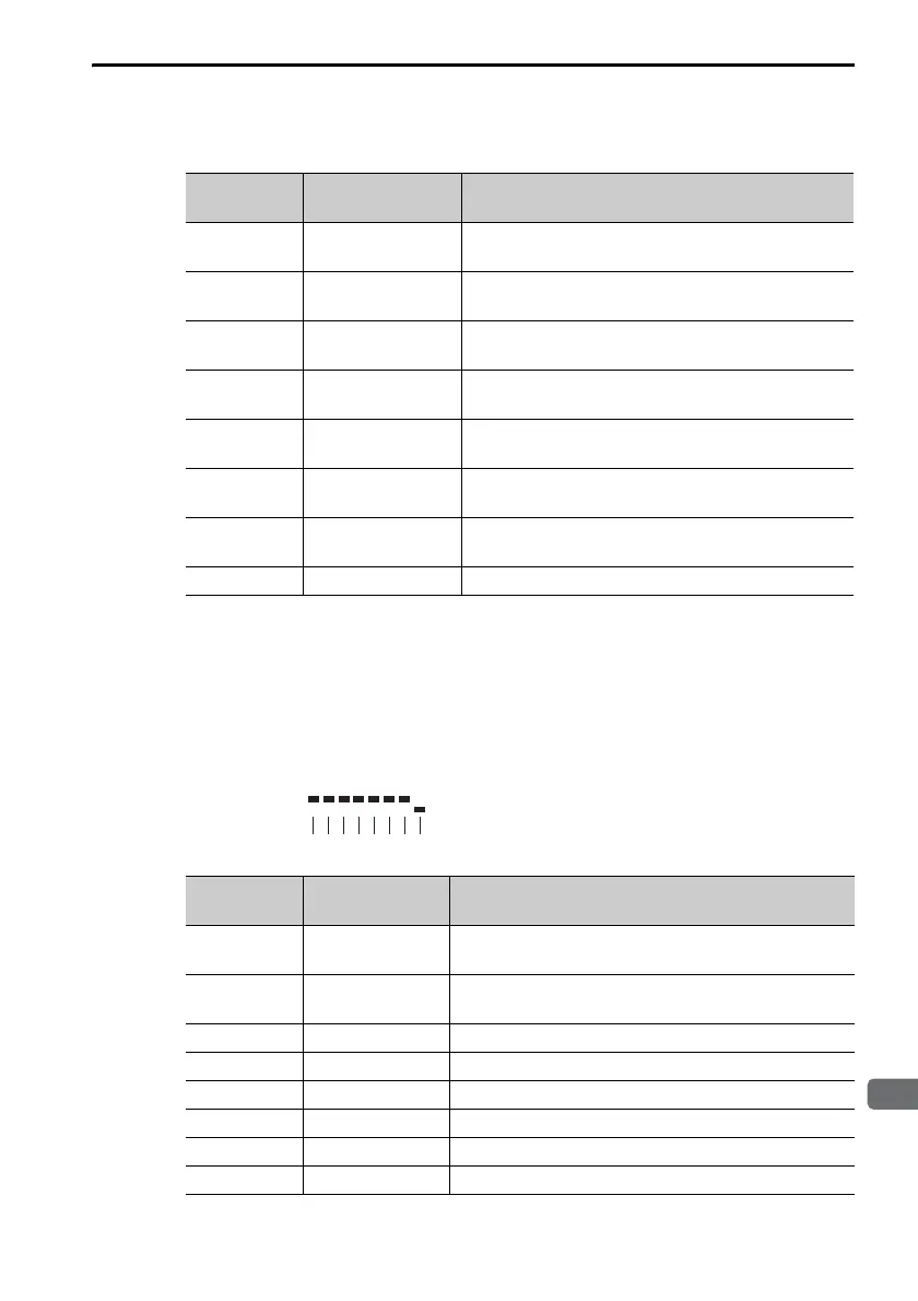
The safety I/O signal monitor (Un015) is displayed as shown below. The
top indicates OFF (high level) and the bottom indicates ON (low level).
Undefined digits are always shown as being ON.
Display Digit
Number
Input Pin
Number
Signal Name
*1
(You can change the allocations.)
1
CN1-19 and
CN1-20
ALM (Servo Alarm) signal for axis 1
*2
2
CN1-21 and
CN1-22
ALM (Servo Alarm) signal for axis 2
*2
3
CN1-23 and
CN1-24
/BK (Brake) signal for axis 1
4
CN1-25 and
CN1-26
/BK (Brake) signal for axis 2
5
CN1-27 and
CN1-28
/SO3 (General-purpose Sequence Output 3)
signal
6
CN1-29 and
CN1-30
/SO4 (General-purpose Sequence Output 4)
signal
7
CN1-31 and
CN1-32
/SO5 (General-purpose Sequence Output 5)
signal
8 – Reserved.
Display Digit
Number
Output Pin
Number
Signal Name
(You cannot change the allocations.)
1
CN8-3 and
CN8-4
/HWBB1 (Hard Wire Base Block Input 1) signal
2
CN8-5 and
CN8-6
/HWBB2 (Hard Wire Base Block Input 2) signal
3 ––
4 ––
5 ––
6 ––
7 ––
8 ––

 Loading...


