146 YASKAWA ELECTRIC EZZ010928 FSDrive-MV1000 Instructions
5.8 LED Indicators on the Controller and CCB (Cell Control Board)
5.8 LED Indicators on the Controller and CCB (Cell Control Board)
The following describes the LED indicators on the controller in the control panel and on the CCB in the Power Cell
panel. These indicators display operation statuses and faults.
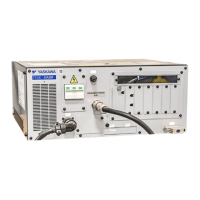
◆ LED Indicators on the Controller
The controller has two types of LED indicators: An LED indicator that displays the controller status, and an LED
indicator that displays the Power Cell status detected by the controller.
Figure 5. 1
Figure 5.1 LED on Controller
• Power Cell Status LEDs
PH_A RANK1 to 5 (Red): Lit when a U-phase rank 1 to 5 Power Cell fault occurs.
PH_B RANK1 to 5 (Red): Lit when a V-phase rank 1 to 5 Power Cell fault occurs.
PH_C RANK1 to 5 (Red): Lit when a W-phase rank 1 to 5 Power Cell fault occurs.
BYPS RANK1 to 5 (Red): Lit when a fault occurs in a rank 1 to 5 Power Cell for bypass.
• Controller Status LEDs
BAT (Red): Lit when the battery voltage has dropped.
ERR (Red): Lit when a fault occurs in the controller.
RUN (Green): Lit when the controller is operating.
PWR (Green): Lit when the control power is on.
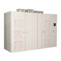
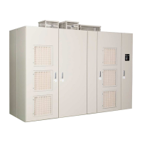
Controller
Drive panel
<Position of the controller> <Status with the controller drawn out>
470
'44
294
2*A%
$#6
2*A$
$;25
2*A#
4#0- 4#0- 4#0- 4#0- 4#0-
Transformer
Controller
%$%$
%$%$ %$%$
%$%$
ᵈᗧᵈᗧ
%#76+10%#76+10
ᵈᗧᵈᗧ
%#76+10%#76+10
ᵈᗧᵈᗧ
%#76+10%#76+10
ᵈᗧᵈᗧ
%#76+10%#76+10
ᵈᗧᵈᗧ
%#76+10%#76+10
ᵈᗧᵈᗧ
%#76+10%#76+10
ᵈᗧߊߛߐޕᵈᗧߊߛߐޕ
2NGCUGFQPQVECVEJVJGHKPIGT2NGCUGFQPQVECVEJVJGHKPIGT
DGVYGGPRCPGNHNCOGCPFVJKUWPKVDGVYGGPRCPGNHNCOGCPFVJKUWPKV
ޓࡄࡀ࡞ࡈ㧙ࡓߣᧄ࡙࠾࠶࠻ߣߩ㑆ߢᜰࠍ߹ߥࠃ߁ߦޓࡄࡀ࡞ࡈ㧙ࡓߣᧄ࡙࠾࠶࠻ߣߩ㑆ߢᜰࠍ߹ߥࠃ߁ߦ
ޓャㅍᤨߩࡂࡦ࠼࡞ᛮߌ㒐ᱛ↪ߦࡄࡀ࡞ࡈ㧙ࡓⓣߣࡂࡦ࠼࡞ޓャㅍᤨߩࡂࡦ࠼࡞ᛮߌ㒐ᱛ↪ߦࡄࡀ࡞ࡈ㧙ࡓⓣߣࡂࡦ࠼࡞
ߩ㑆ߦ⚿᧤ࡃࡦ࠼╬ࠍᏎ߈ઃߌߡߐޕߩ㑆ߦ⚿᧤ࡃࡦ࠼╬ࠍᏎ߈ઃߌߡߐޕ
2NGCUGFQPQVECVEJVJGHKPIGT2NGCUGFQPQVECVEJVJGHKPIGT
DGVYGGPRCPGNHNCOGCPFVJKUWPKVDGVYGGPRCPGNHNCOGCPFVJKUWPKV
㧴㧝㧴㧝
㧴㧞㧴㧞
㨀㨀
㧴㧟㧴㧟
(Draw-out
construction)
Transformer Transformer

 Loading...


