Parameter Details
5
5.2 b: Application
YASKAWA SIEPYAIH6B01A HV600 AC Drive Bypass Technical Reference 215
■ b5-01: PID Mode Setting
No.
(Hex.)
Name Description
Default
(Range)
b5-01
(01A5)
PID Mode Setting Sets the type of PID control. 0
(0 - 3)
0 : Disabled
1 : Standard
The drive does D control on the difference between the feedback value and the PID setpoint output through U5-02
[PID Input].
3 : Fref + PID Trim
The drive adds the frequency reference to the PID output. The drive does D control on the difference between the
feedback value and the PID setpoint output through U5-02.
Note:
• When you set b5-01 = 1 or 3 from the keypad, the drive will automatically set H3-10 = B [Terminal A2 Function Selection = PID
Feedback] and o1-26 = 501 [Custom Monitor 3 = PID Feedback]. The drive will also update the defaults for H3-10 and o1-26 when you
change b5-01.
• When you set b5-01 = 0 from the keypad, the drive will automatically set H3-10 = 0 [Frequency Reference] and o1-26 = 103 [Output
Current].
• When you set b5-01 from a different method, for example MEMOBUS, the drive will automatically update the defaults for H3-10 and o1-
26, but it will not update the parameters.
■ b5-02: Proportional Gain (P)
No.
(Hex.)
Name Description
Default
(Range)
b5-02
(01A6)
RUN
Proportional Gain (P) Sets the proportional gain (P) that is applied to PID input. 2.00
(0.00 - 25.00)
Larger values decrease errors, but can cause oscillations. Smaller values let too much offset between the setpoint and
feedback.
Set b5-02 = 0.00 to disable P control.
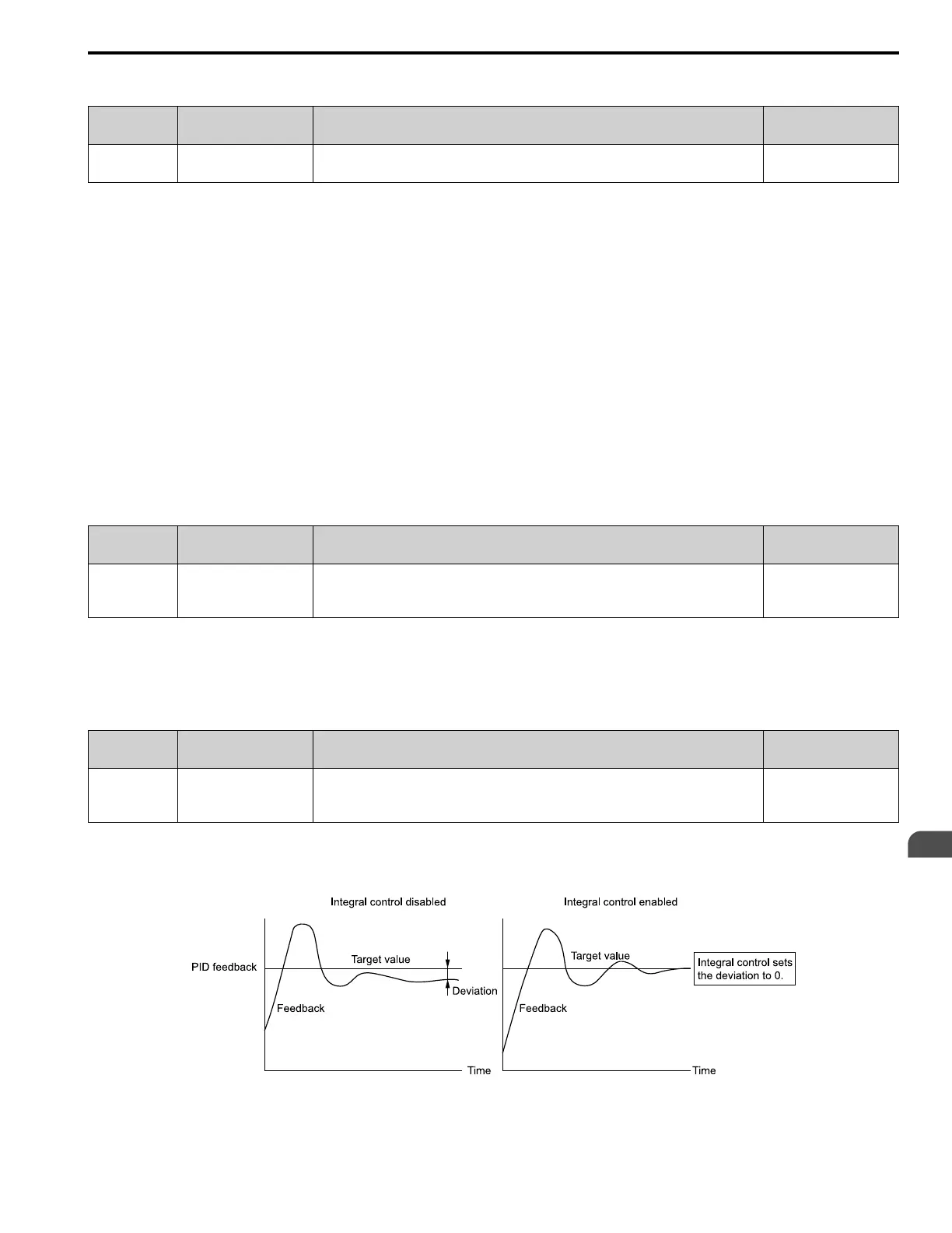
■ b5-03: Integral Time (I)
No.
(Hex.)
Name Description
Default
(Range)
b5-03
(01A7)
RUN
Integral Time (I) Sets the integral time (I) that is applied to PID input. 0.5 s
(0.0 - 360.0 s)
Set a short integral time in b5-03 to remove the offset faster. If the integral time is too short, it can cause overshoot or
oscillation.
Set b5-03 = 0.0 to disable I control.
Figure 5.25 Integral Time and Deviation

 Loading...


