Electrical Installation
3
3.3 Main Circuit Wiring
YASKAWA SIEPYAIH6B01A HV600 AC Drive Bypass Technical Reference 79
3.3 Main Circuit Wiring
This section gives information about the functions, specifications, and procedures necessary to safely and correctly
wire the main circuit in the bypass.
NOTICE: Damage to Equipment. Do not energize and de-energize the bypass more frequently than one time each 30 minutes. If
you frequently energize and de-energize the bypass, it can cause failure.
Note:
Soldered wire connections can become loose over time and cause unsatisfactory performance.
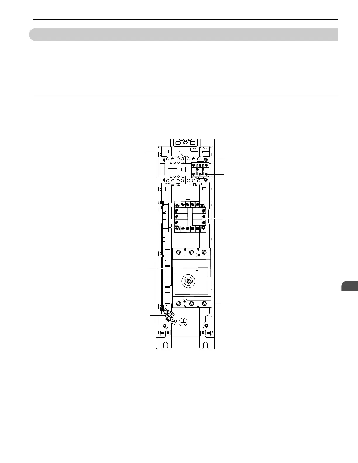
◆ Narrow Bypass Input and Output Power Wiring Connections
The input disconnect switch is located in the upper right hand side of the bypass. The three-phase input power
connection is made to the input terminals of the disconnect. Refer to Figure 3.3 for a representative example. Motor
Terminal Block TB1 is mounted to the contactor assembly or back panel (depending on rating), just above the bypass
contactor. The bypass three-phase output power connection to the motor is made to Terminal Block TB1.
Note:
The location of components are different for different bypass models.
A - Drive output contactor K2
B - Input contactor K1
C - Motor connections
D - Input power terminals
E - Ground screw
F - A2 bypass control board
G - 120 V control transformer
H - Bypass contactor K3
Figure 3.3 Narrow Bypass Circuit Components Example