Parameter Details
5
5.2 b: Application
YASKAWA SIEPYAIH6B01A HV600 AC Drive Bypass Technical Reference 187
5.2 b: Application
b parameters set these functions:
• Frequency reference source/Run command source
• Stopping method settings
• DC Injection Braking
• Speed Search
• Timer Function
• PID control
• Energy Savings Control
◆ b1: Operation Mode Selection
b1 parameters set the operation mode for the drive.
■ b1-01: Frequency Reference Selection 1
No.
(Hex.)
Name Description
Default
(Range)
b1-01
(0180)
Frequency Reference
Selection 1
Sets the input method for the frequency reference. 1
(0 - 3)
Note:
• Push on the keypad to set the input mode to HAND and enter the frequency reference from the keypad.
• When the drive receives a Run command when the frequency reference is 0 Hz or less than the E1-09 [Minimum Output Frequency] value,
on the keypad will flash. Examine the setting for the frequency reference input and enter a value ≥ E1-09.
0 : Keypad
The bypass uses the keypad to enter the frequency reference and also switches the PID setpoint to YA-01 [Setpoint 1].
Use and on the keypad to change the frequency reference.
1 : Analog Input
The bypass uses MFAI on the bypass board to input an analog frequency reference with a voltage or current input
signal.
• Voltage Input
Refer to Table 5.18 to use a voltage signal input to one of the MFAI terminals.
Table 5.18 Frequency Reference Voltage Input
Terminal Terminal Signal Level
Parameter Settings
Note
Signal Level Selection Gain Bias
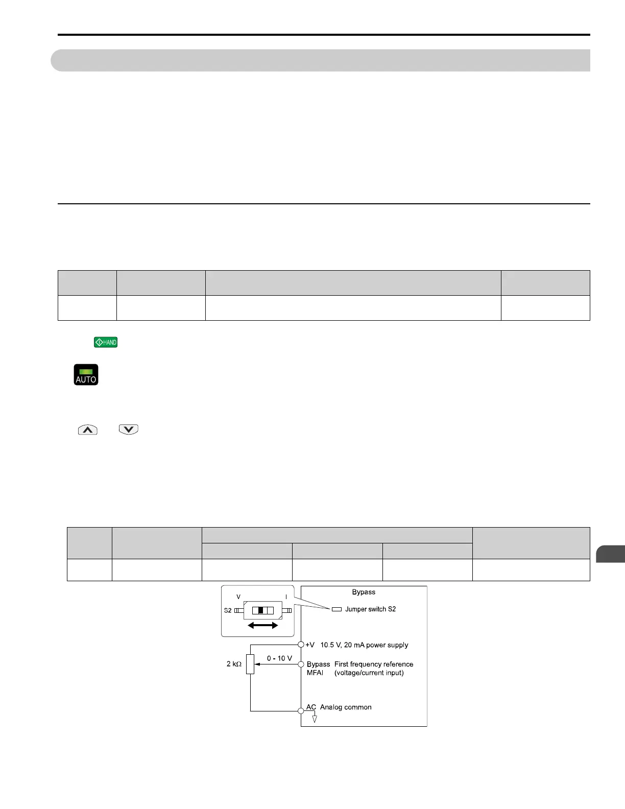
Bypass MFAI 0 - 10 V Z2-30 = 0 Z2-32 Z2-33 Set Jumper Switch S2 to “V” for
voltage input.
Figure 5.1 Example of Setting the Frequency Reference with a Voltage Signal to the Bypass MFAI

 Loading...


