Mechanical Installation
2
2.3 Installation Positions and Clearances
YASKAWA SIEPYAIH6B01A HV600 AC Drive Bypass Technical Reference 35
2.3 Installation Positions and Clearances
◆ Narrow Bypass Installation Position and Clearances
■ Installation Dimensions
Refer to the Dimension Drawing (DD.HB.x.xx.xx) packaged with the bypass for exterior and mounting dimensions
for your model.
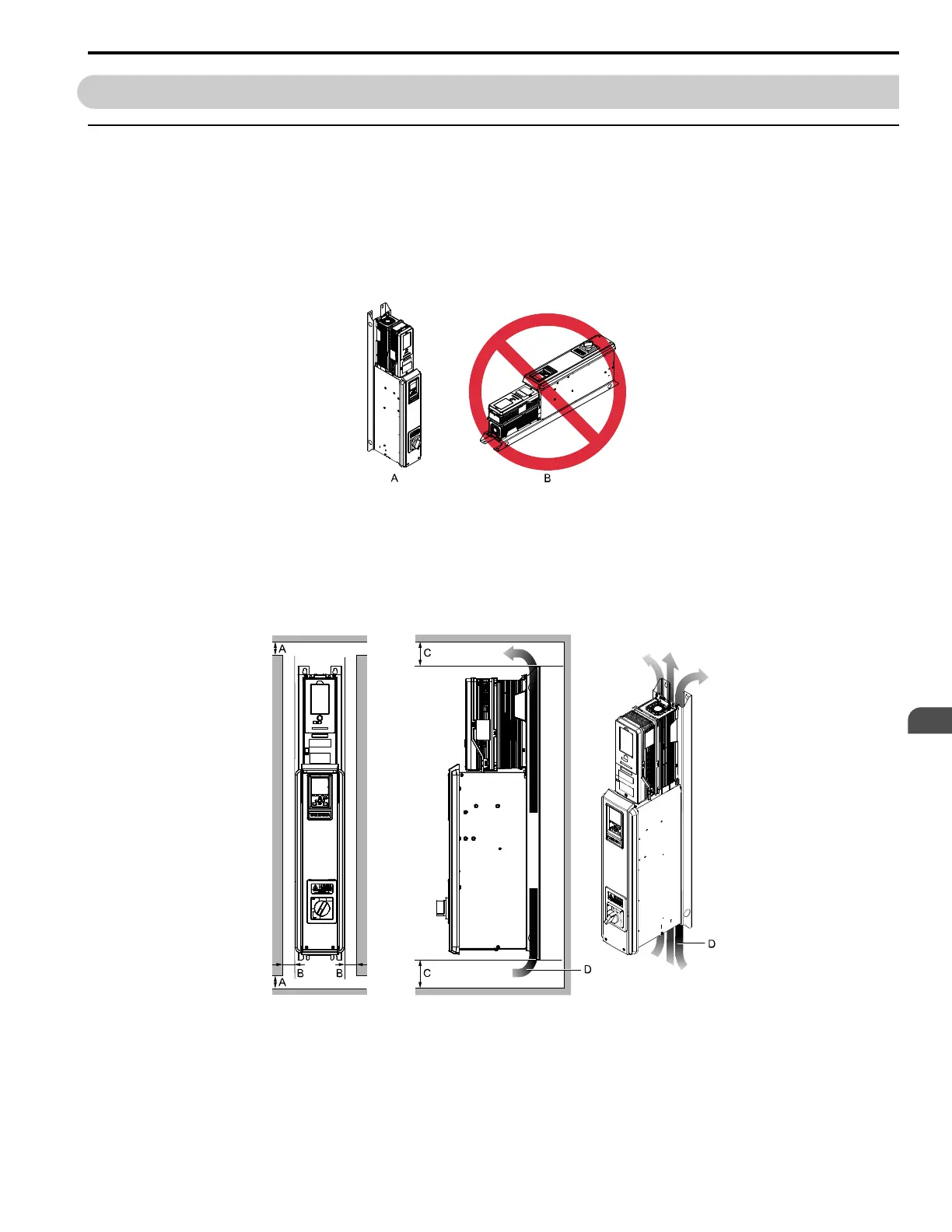
■ Installation Position
Install the bypass vertically for sufficient cooling airflow.
A - Vertical installation B - Horizontal installation
Figure 2.1 Installation Position
■ Single Narrow Bypass Installation Clearances
Use the clearances specified in Figure 2.2 to install the bypass. Make sure that there is sufficient space for wiring and
airflow.
A - 50 mm (2 in) minimum
B - 30 mm (1.2 in) minimum
C - 120 mm (4.7 in) minimum
*1
D - Airflow direction
Figure 2.2 Single Bypass Installation
*1 This is the distance from a component or mounting bracket that has the maximum height. The highest component is different for different
models.