Electrical Installation
3
3.6 Drive PCB Control Circuit
YASKAWA SIEPYAIH6B01A HV600 AC Drive Bypass Technical Reference 99
3.6 Drive PCB Control Circuit
Note:
When possible, use the control terminal connections on the Bypass PCB. The additional control I/O terminals available on the Drive Control
PCB, are active in Drive Mode ONLY and may not report correctly in Bypass Mode. Typically, the Drive Control PCB wiring is used with a
PID feedback signal or an analog monitor (output).
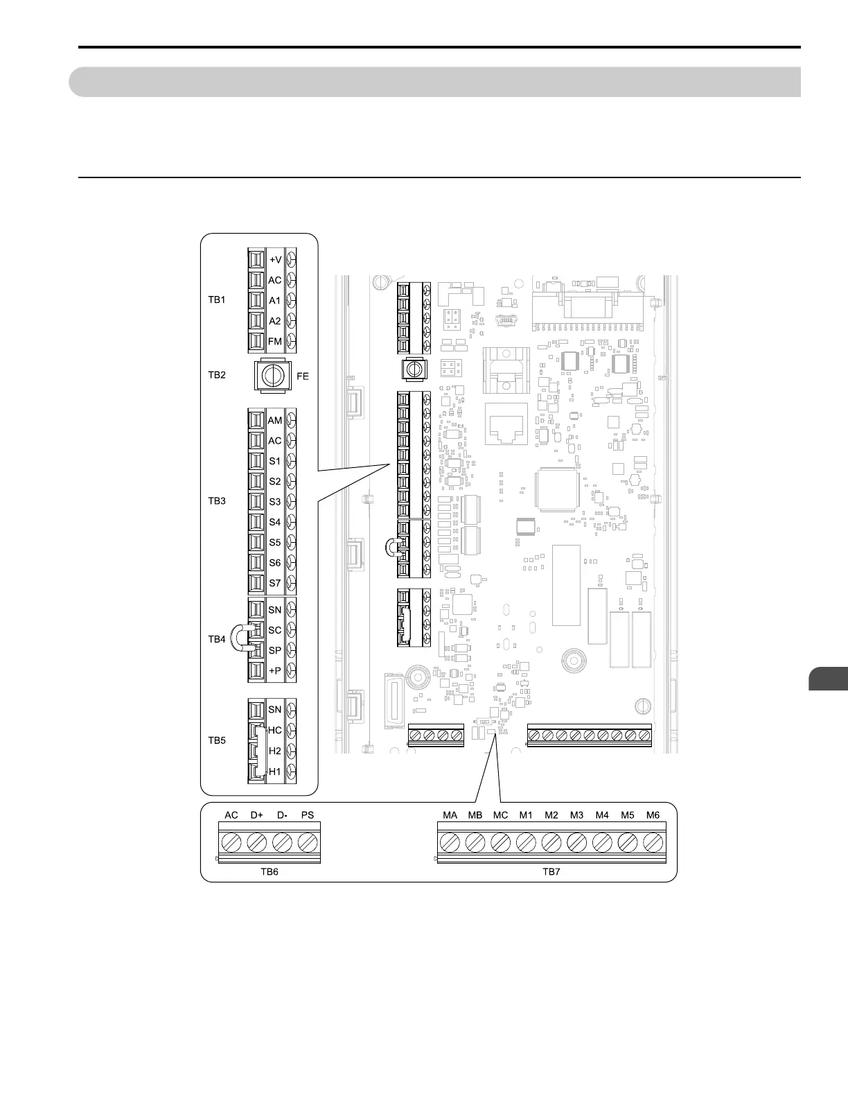
◆ Control Circuit Terminal Arrangement
The drive control circuit terminals are in the positions shown in Figure 3.14.
Figure 3.14 Drive Control Circuit Terminal Arrangement
The tightening torque for the drive terminal screws is shown on the reverse side or the lower front side of the drive
front cover.