3.6 Drive PCB Control Circuit
100 YASKAWA SIEPYAIH6B01A HV600 AC Drive Bypass Technical Reference
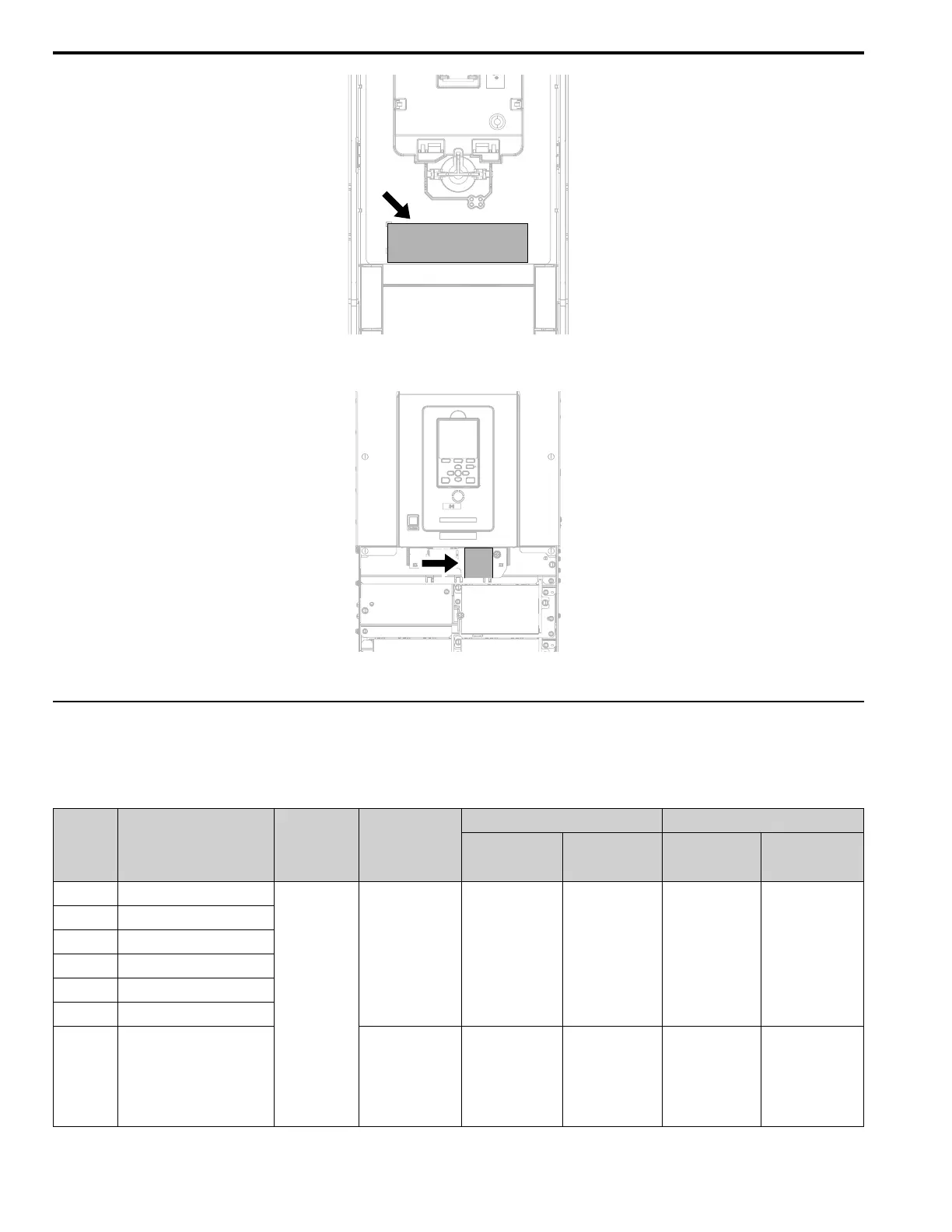
Figure 3.15 Tightening Torque Display Location (Reverse Side of Drive Front Cover)
Figure 3.16 Tightening Torque Display Location (Lower Front Side of Drive Front Cover)
◆ Control Circuit Wire Gauges and Tightening Torques
Use the tables in this section to select the correct wires. Use shielded wire to wire the control circuit terminal block.
Use crimp ferrules on the wire ends to make the wiring procedure easier and more reliable.
Table 3.20 Control Circuit Wire Gauges and Tightening Torques
Drive
Terminal
Block
Terminal Screw Size
Tightening Torque
N∙m (in∙lb)
Bare Wire Crimp Ferrule
Recommended
Gauge
mm
2
(AWG)
Applicable Gauge
mm
2
(AWG)
Recommended
Gauge
mm
2
(AWG)
Applicable Gauge
mm
2
(AWG)
TB1 +V, AC, A1, A2, FM
M3
0.5 - 0.6
(4.4 - 5.3)
0.75
(18)
Stranded wire:
0.25 - 1.5
(24 - 16)
Solid wire:
0.25 - 1.5
(24 - 16)
0.75
(18)
0.25 - 1.5
(24 - 16)
TB3 AM, AC, S1 - S7
TB4 SN, SC, SP, +P
TB5 SN, HC, H1, H2
TB6 AC, D+, D-, PS
TB7 MA, MB, MC, M1 - M6
TB2 FE
1.0 - 1.2
(8.85 - 10.62)
0.75
(18)
Stranded wire:
0.12 - 0.75
(26 - 18)
Solid wire:
0.2 - 1.5
(26 - 16)
0.75
(18)
0.25 - 1.5
(24 - 16)