Electrical Installation
3
3.6 Drive PCB Control Circuit
YASKAWA SIEPYAIH6B01A HV600 AC Drive Bypass Technical Reference 101
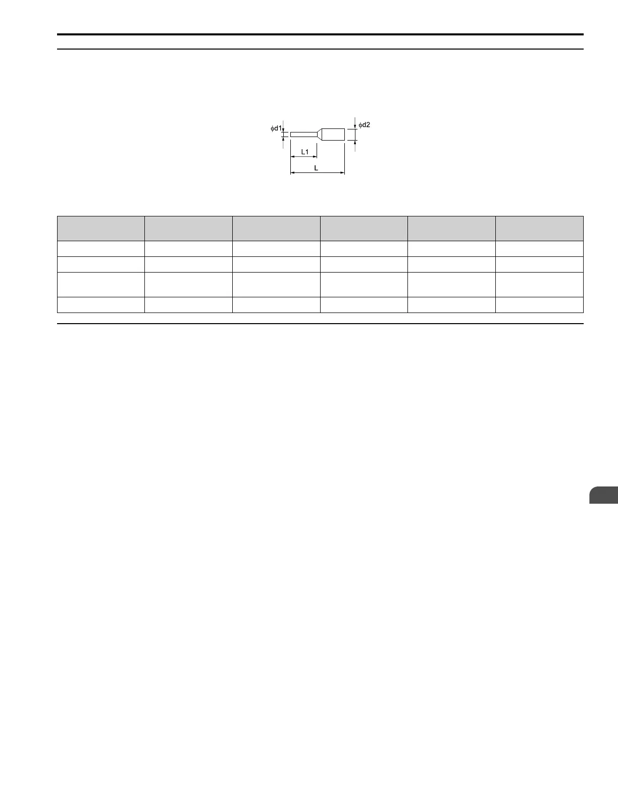
◆ Crimp Ferrules
Attach an insulated sleeve when you use crimp ferrules. Refer to Table 3.21 for the recommended external
dimensions and model numbers of the crimp ferrules.
Use the CRIMPFOX 6, a crimping tool made by PHOENIX CONTACT.
Figure 3.17 External Dimensions of Crimp Ferrules
Table 3.21 Crimp Ferrule Models and Sizes
Wire Gauge
mm
2
(AWG)
Model L (mm) L1 (mm) φd1 (mm) φd2 (mm)
0.25 (24) AI 0.25-8YE 12.5 8 0.8 2.0
0.34 (22) AI 0.34-8TQ 12.5 8 0.8 2.0
0.5 (20)
AI 0.5-8WH
AI 0.5-8OG
14 8 1.1 2.5
0.75 (18) AI 0.75-8 GY 14 8 1.3 2.8
◆ Control Circuit Terminal Block Input Functions
Hx-xx parameters set functions for the multi-function input and output terminals.
WARNING! Sudden Movement Hazard. Correctly wire and test all control circuits to make sure that the control circuits operate
correctly. If you use a drive that has incorrect control circuit wiring or operation, it can cause death or serious injury.
WARNING! Sudden Movement Hazard. Check the I/O signals and the external sequences for the drive before you set the
Application Preset function. When you set the Application Preset function (A1-06 ≠ 0), it changes the I/O terminal functions for the
drive and it can cause equipment to operate unusually. This can cause serious injury or death.
NOTICE: Damage to Equipment. Do not energize and de-energize the bypass more frequently than one time each 30 minutes. If
you frequently energize and de-energize the bypass, it can cause failure.
Refer to Table 3.22 for a list of input terminals and functions on the drive.