EasyManuals Logo

YASKAWA HV600 User Manual

YASKAWA HV600
794 pages
To Next Page IconTo Next Page
To Previous Page IconTo Previous Page
Page #40 background imageLoading...
Page #40 background image
2.5 Bypass Component Names
40 YASKAWA SIEPYAIH6B01A HV600 AC Drive Bypass Technical Reference
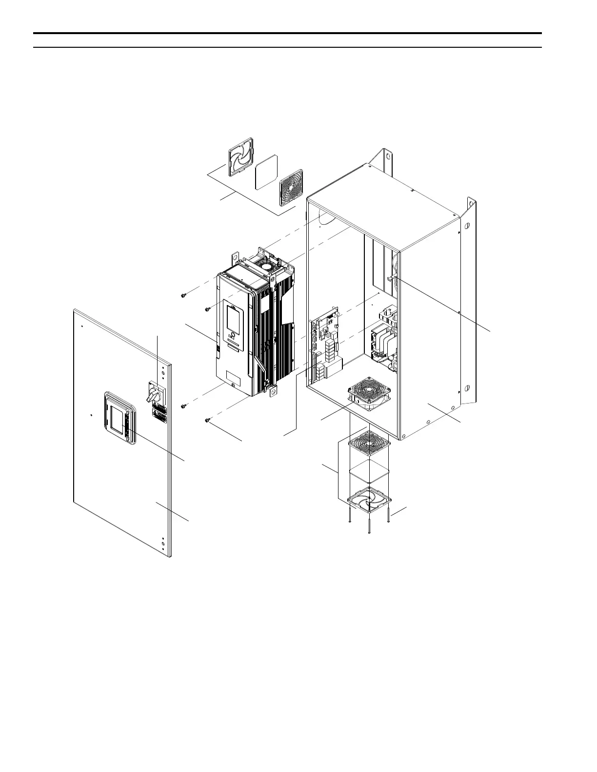
â—† Enclosed Bypass Component Names
This section gives an overview of the Enclosed Bypass components described in this manual.
â–  208 V Enclosed Models: H6B1D002 to D273
240 V Enclosed Models: H6B1A002 to A248
480 V Enclosed Models: H6B1B001 to B302
A - Disconnect shaft
B - Bypass enclosure
C - Fan mounting screws
D - Fan cover assembly
E - Bypass enclosure fan
F - Bypass PCB
G - Drive mounting screws
H - HOA keypad
I - Bypass enclosure front door
J - Disconnect switch
K - HV600 drive
Figure 2.7 Exploded View of Components (Enclosed Model D046 Example)
A
B
I
H
G
C
D
J
K
D
F
E

Table of Contents

Other manuals for YASKAWA HV600

Questions and Answers:

Question and Answer IconNeed help?

Do you have a question about the YASKAWA HV600 and is the answer not in the manual?

YASKAWA HV600 Specifications

General IconGeneral
CategoryDC Drives
SeriesHV600
Overload Capacity150% for 60 seconds
Output Voltage0 - Input Voltage
EnclosureNEMA 1, NEMA 12
CommunicationEthernet/IP, Modbus, DeviceNet, Profibus
SafetySafe Torque Off (STO)
Protection FeaturesOvercurrent, Overvoltage, Undervoltage, Short Circuit
Humidity5-95% (non-condensing)
AltitudeUp to 1000m (3280ft) without derating
Control MethodVector Control

Related product manuals