3.5 Bypass PCB Control Circuit
98 YASKAWA SIEPYAIH6B01A HV600 AC Drive Bypass Technical Reference
Note:
• Refer to Figure 3.13 for information to prepare terminal ends of the shielded wire.
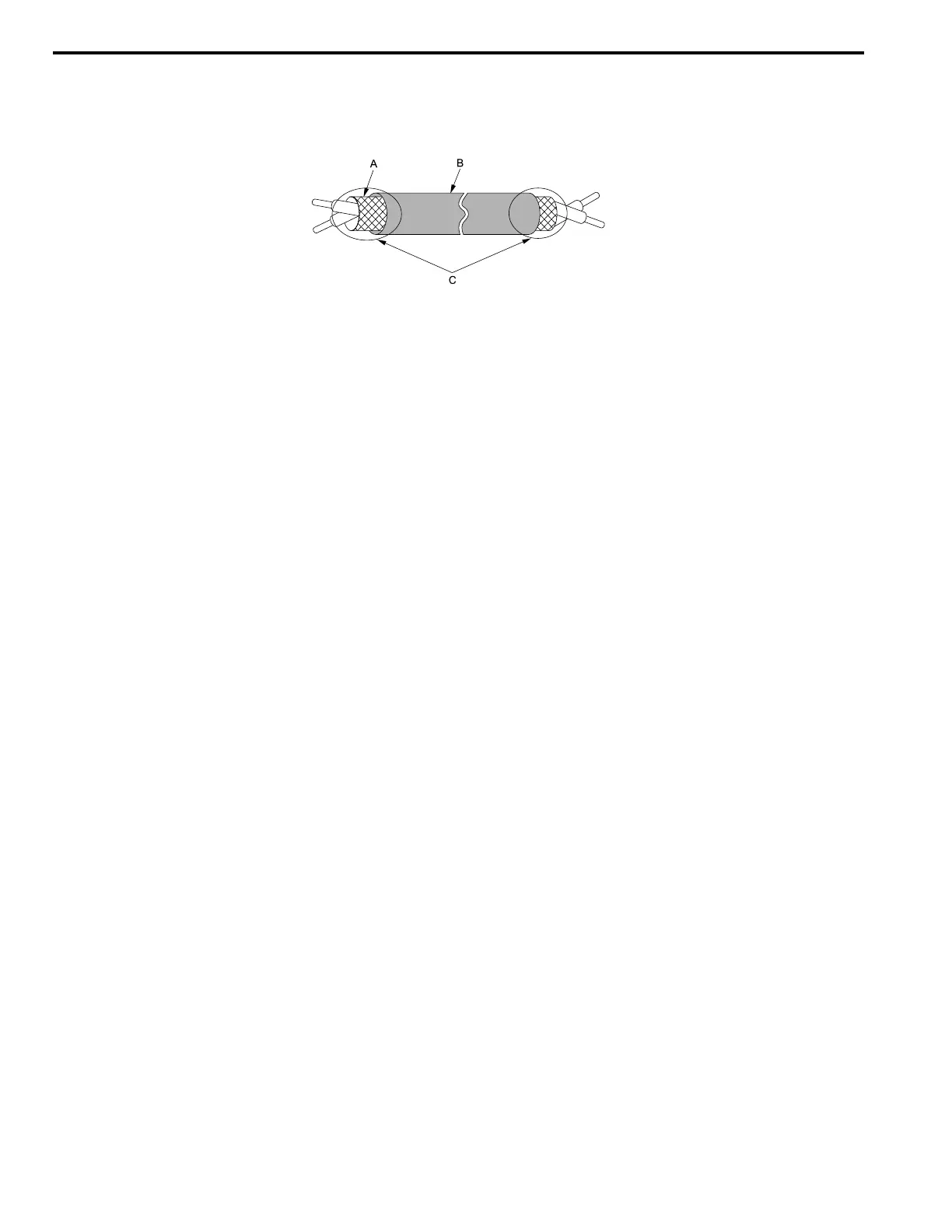
• Prepare the wire ends of shielded twisted-pair wires as shown in Figure 3.13 to use an analog reference from an external
frequency setting potentiometer to set the frequency. Connect the shield to TB2-11 or TB2-12 on the bypass control board or
terminal FE on the drive.
A - Connect the shield to TB2-11 or TB2-12.
B - Sheath
C - Insulate with electrical tape or shrink tubing.
Figure 3.13 Prepare the Ends of Shielded Wire
2. Install the front cover to its initial position.