5.2 b: Application
224 YASKAWA SIEPYAIH6B01A HV600 AC Drive Bypass Technical Reference
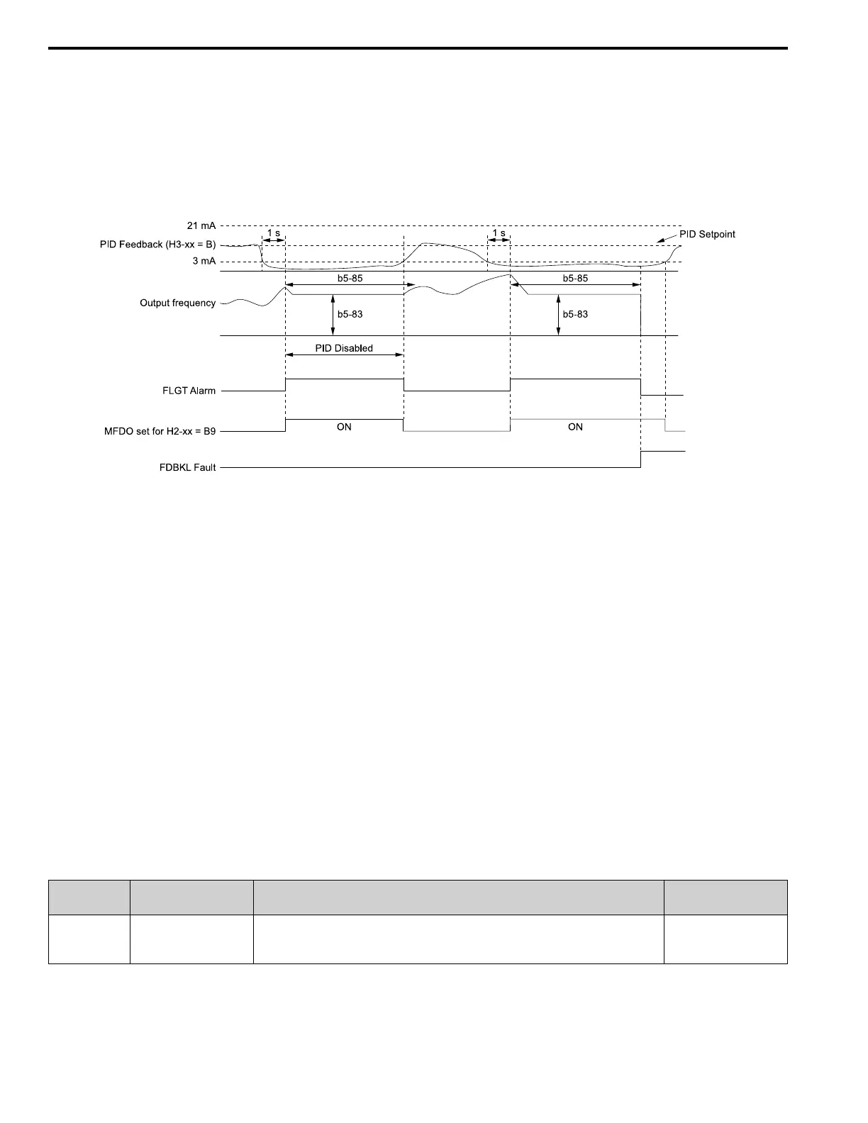
PID Feedback Loss Go To Frequency Timeout
The drive will apply this feature only when b5-82 = 3 [Run At b5-83] and it detects a Feedback Loss. Parameter b5-
85 [Feedback Loss GoTo Freq Timeout] sets the length of time that the drive will run at the frequency set in b5-83
[Feedback Loss GoTo Frequency].
• When b5-85 = 0 sec, the drive will operate at the b5-83 speed indefinitely.
• When b5-85 > 0 sec, the drive will only operate at the b5-83 speed for the time specified in b5-85, after which the
drive will fault on an FDBKL [WIRE Break] fault.
Refer to Figure 5.28 for more information.
b5-83: Feedback Loss GoTo Frequency
b5-85: Feedback Loss GoTo Freq Timeout
b5-86: Feedback Loss Start Delay
H2-xx = B9: Transducer Loss
H3-xx = B: PID Feedback
FDBKL Fault: WIRE Break
FLGT Alarm: Feedback Loss, Go To Freq b5-83
Figure 5.28 Time Chart for the Wire Break Detection when b5-82 = 3
Backup PID Feedback Transducer Input
When you set H3-xx = 24 [MFAI Function Selection = PID Feedback Backup], the drive will activate the PID
Feedback Backup signal.
• If the primary PID Feedback (H3-xx = B [PID Feedback]) is lost, the system will automatically use the backup PID
Feedback from the MFAI terminal set for H3-xx = 24 and flash a Bu-Fb [Main Fdbk Lost Using Backup Fdbk]
alarm.
• If the main PID Feedback is operational, but the backup PID Feedback is lost, the drive will show a BuFbl [Backup
Fdbk Lost Chk/Repl Xducer] alarm. If the main and backup PID Feedback devices are lost, the drive will use the
b5-82 [Feedback Loss 4~20mA Detect Sel] setting.
Note:
To enable the FDBKL [WIRE Break] detection correctly, use a 4 to 20 mA operation in these conditions:
• Use a 4 to 20 mA signal for transducers.
• Program the drive analog inputs and set Jumper Switch S1 to “I” for current input.
If you set the analog input for voltage, the drive will disable the detection mechanism.
■ b5-83: Feedback Loss GoTo Frequency
No.
(Hex.)
Name Description
Default
(Range)
b5-83
(31B1)
RUN
Feedback Loss GoTo
Frequency
Sets the speed at which the drive will run if the drive detects a 4 to 20 mA wire-break on the PID
Feedback and b5-82 = 3 [Feedback Loss 4~20mA Detect Sel = Run At b5-83].
0.0 Hz
(0.0 - 400.0 Hz)

 Loading...


