Parameter Details
5
5.7 H: Terminal Functions
YASKAWA SIEPYAIH6B01A HV600 AC Drive Bypass Technical Reference 281
L4-02: Speed Agree Detection Width
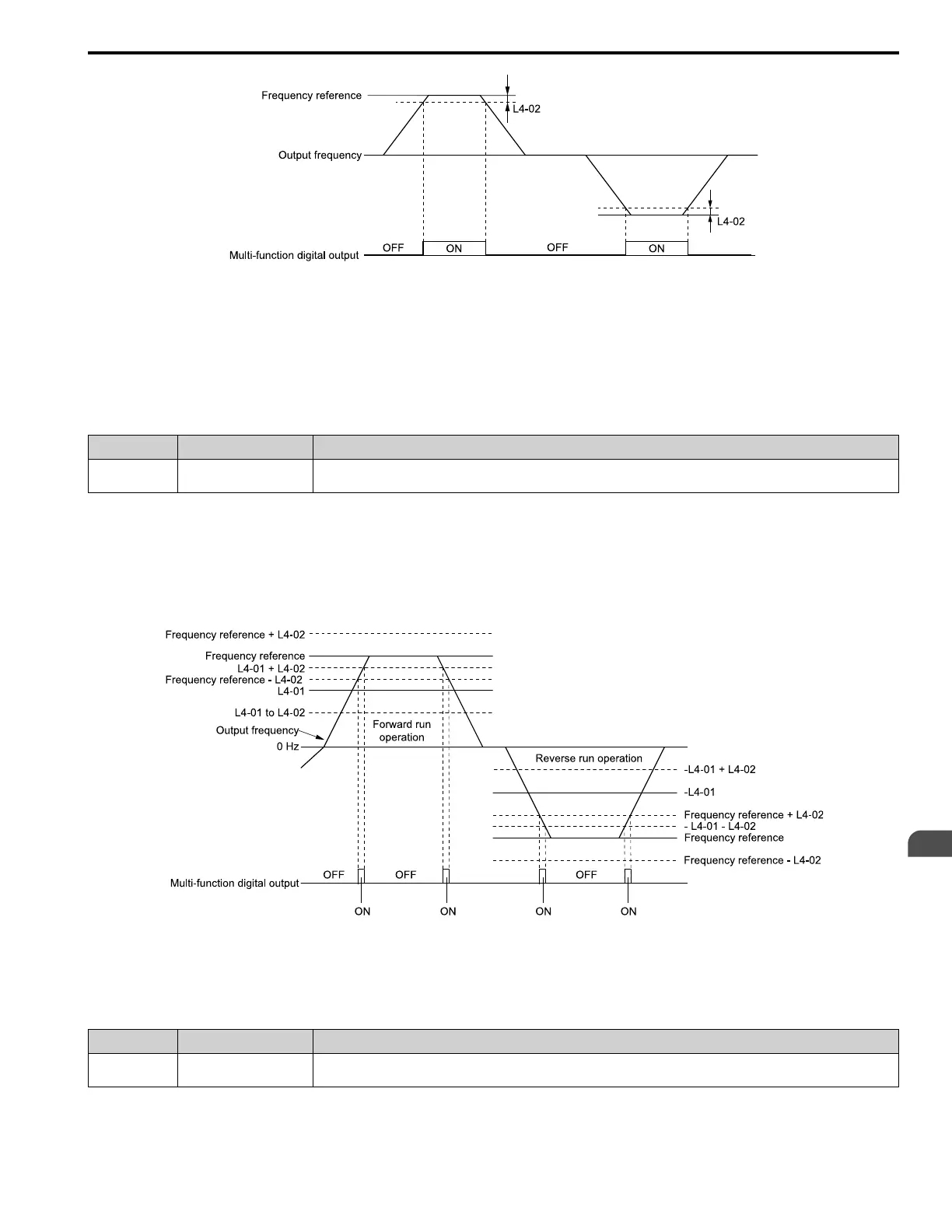
Figure 5.48 Speed Agree 1 Time Chart
ON : The output frequency is in the range of “frequency reference ± L4-02”.
OFF : The output frequency does not align with the frequency reference although the drive is
running.
■ 3: User-Set Speed Agree 1
Setting Value Function Description
3 User-Set Speed Agree 1 The terminal activates when the output frequency is in the range of L4-01 [Speed Agree Detection Level] ± L4-02 [Speed Agree
Detection Width] and in the range of the frequency reference ± L4-02.
Note:
The detection function operates in the two motor rotation directions. The drive uses the L4-01 value as the forward/reverse detection level.
ON : The output frequency is in the range of “L4-01 ± L4-02” and the range of frequency reference ±
L4-02.
OFF : The output frequency is not in the range of “L4-01 ± L4-02” or the range of frequency
reference ± L4-02.
L4-01: Speed Agree Detection Level L4-02: Speed Agree Detection Width
Figure 5.49 User-Defined Speed Agree 1 Time Chart
■ 4: Frequency Detection 1
Setting Value Function Description
4 Frequency Detection 1 The terminal deactivates when the output frequency > “L4-01 [Speed Agree Detection Level] + L4-02 [Speed Agree Detection
Width]”. After the terminal deactivates, the terminal stays deactivated until the output frequency is at the value of L4-01.
Note:
The detection function operates in the two motor rotation directions. The drive uses the L4-01 value as the forward/reverse detection level.
 Loading...


