5.7 H: Terminal Functions
284 YASKAWA SIEPYAIH6B01A HV600 AC Drive Bypass Technical Reference
■ 10: Alarm
Setting Value Function Description
10 Alarm The terminal activates when the drive detects a minor fault.
■ 11: Fault Reset Command Active
Setting Value Function Description
11 Fault Reset Command
Active
The terminal activates when the drive receives the Reset command from the control circuit terminal, serial communications, or the
communication option.
■ 12: Timer Output
Setting Value Function Description
12 Timer Output Use this setting when the drive uses the timer function as an output terminal.
Note:
Refer to Timer Function Operation on page 206 for more information.
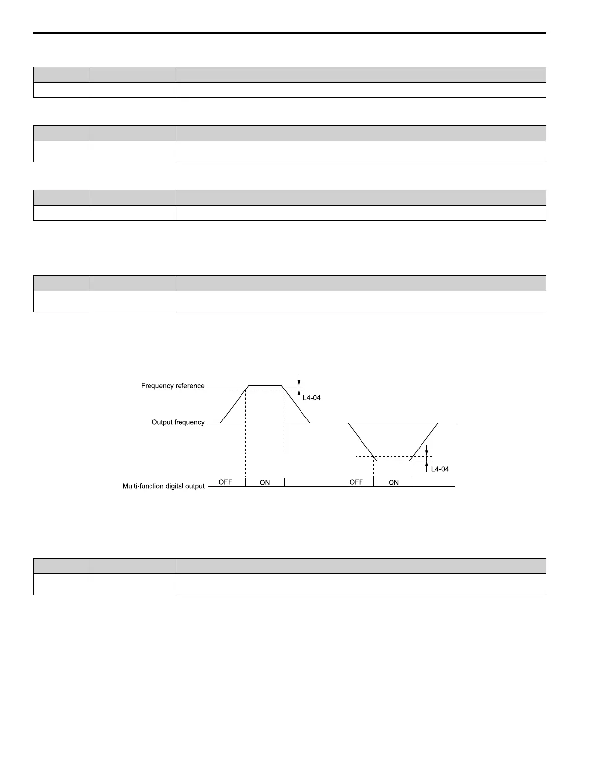
■ 13: Speed Agree 2
Setting Value Function Description
13 Speed Agree 2 The terminal activates when the output frequency is in the range of the frequency reference ± L4-04 [Speed Agree Detection Width
(+/-)].
Note:
The detection function operates in the two motor rotation directions.
ON : The output frequency is in the range of “frequency reference ± L4-04”.
OFF : The output frequency is not in the range of “frequency reference ± L4-04”.
L4-04: Speed Agree Detection Width(+/-)
Figure 5.52 Speed Agree 2 Time Chart
■ 14: User-Set Speed Agree 2
Setting Value Function Description
14 User-Set Speed Agree 2 The terminal activates when the output frequency is in the range of L4-03 [Speed Agree Detection Level (+/-)] ± L4-04 [Speed
Agree Detection Width (+/-)] and in the range of the frequency reference ± L4-04.
Note:
The detection level set in L4-03 is a signed value. The drive will only detect in one direction.
ON : The output frequency is in the range of “L4-03 ± L4-04” and the range of frequency reference ±
L4-04.
OFF : The output frequency is not in the range of “L4-03 ± L4-04” or the range of frequency
reference ± L4-04.

 Loading...


