Parameter Details
5
5.7 H: Terminal Functions
YASKAWA SIEPYAIH6B01A HV600 AC Drive Bypass Technical Reference 285
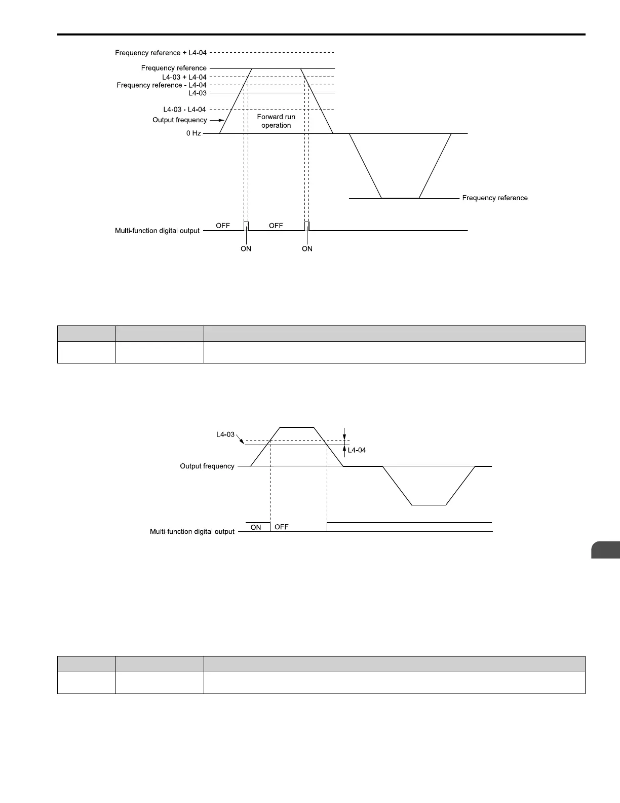
L4-03: Speed Agree Detection Level(+/-) L4-04: Speed Agree Detection Width(+/-)
Figure 5.53 Example of User-set Speed Agree 2 (L4-03 Is Positive)
■ 15: Frequency Detection 3
Setting Value Function Description
15 Frequency Detection 3 The terminal deactivates when the output frequency > “L4-03 [Speed Agree Detection Level (+/-)] + L4-04 [Speed Agree Detection
Width (+/-)]”. After the terminal deactivates, the terminal stays deactivated until the output frequency is at the value of L4-03.
Note:
The detection level set in L4-03 is a signed value. The drive will only detect in one direction.
ON : The output frequency < L4-03, or the output frequency ≤ L4-03 + L4-04.
OFF : The output frequency > “L4-03 + L4-04”.
L4-03: Speed Agree Detection Level(+/-) L4-04: Speed Agree Detection Width(+/-)
Figure 5.54 Example of Frequency Detection 3 (Value of L4-03 is Positive)
Note:
Figure 5.54 shows the time chart when L4-07 = 1 [Speed Agree Detection Selection = Detection Always Enabled]. The default setting of L4-
07 is 0 [No Detection during Baseblock]. When the speed agreement detection selection is “No Detection during Baseblock”, the terminal
deactivates when the drive output stops.
■ 16: Frequency Detection 4
Setting Value Function Description
16 Frequency Detection 4 The terminal activates when the output frequency > L4-03 [Speed Agree Detection Level (+/-)]. After the terminal activates, the
terminal stays activated until the output frequency is at the value of “L4-03 - L4-04”.
Note:
The detection level set in L4-03 is a signed value. The drive will only detect in one direction.
ON : The output frequency > L4-03.
 Loading...


