Parameter Details
5
5.7 H: Terminal Functions
YASKAWA SIEPYAIH6B01A HV600 AC Drive Bypass Technical Reference 301
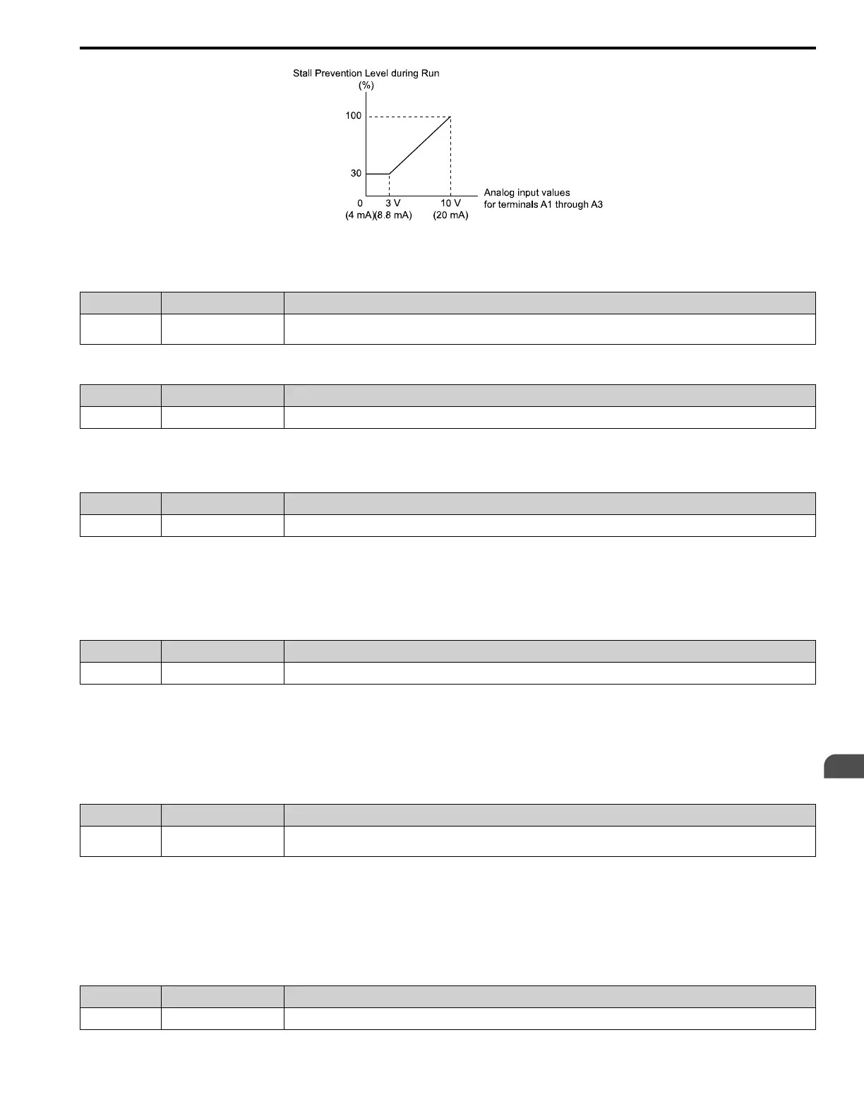
Figure 5.62 Stall Prevention Level during Run with Analog Input
■ 9: Output Frequency Lower Limit
Setting Value Function Description
9 Output Frequency Lower
Limit
Enters a signal to adjust the output frequency lower limit level as a percentage of the maximum output frequency.
■ B: PID Feedback
Setting Value Function Description
B PID Feedback Enter the PID feedback value as a percentage of the maximum output frequency.
When you use this function, set b5-01 ≠ 0 [PID Mode Setting ≠ Disabled].
■ C: PID Setpoint
Setting Value Function Description
C PID Setpoint Enters the PID setpoint as a percentage of the maximum output frequency.
When you use this function, set b5-01 ≠ 0 [PID Mode Setting ≠ Disabled].
Note:
Configuring this function disables the frequency reference set with b1-01 [Frequency Reference Selection 1].
■ D: Frequency Bias
Setting Value Function Description
D Frequency Bias Enters the bias value added to the frequency reference as a percentage of the maximum output frequency.
The drive adds the input value from the MFAI terminal set with this function to the frequency reference as the bias
value.
Note:
When you select d1-01 to d1-17 [Reference 1 to 8 or JOG Frequency Reference] as the frequency reference, it will disable this function.
■ E: Motor Temperature (PTC Input)
Setting Value Function Description
E Motor Temperature (PTC
Input)
Uses the motor Positive Temperature Coefficient (PTC) thermistor to prevent heat damage to the motor as a percentage of the
current value when the 10 V analog signal is input.
• You can use the Positive Temperature Coefficient (PTC) thermistor as an auxiliary or alternative detection function
for oL1 [Motor Overload] problems to help prevent heat damage to motors. If the PTC input signal is more than the
overload alarm level, oH3 [Motor Overheat (PTC Input)] will flash on the keypad.
• When the drive detects oH3, the motor stops with the setting in L1-03. When the drive detects oH4, the motor stops
with the setting in L1-04. When the drive incorrectly detects motor overheating problems, set L1-05.
■ F: Not Used
Setting Value Function Description
F Not Used Use this setting for unused terminals or to use terminals in through mode.