5.8 L: Protection Functions
324 YASKAWA SIEPYAIH6B01A HV600 AC Drive Bypass Technical Reference
Note:
The function to automatically reduce the stall prevention level does not operate when L3-01 = 3 [Stall Prevention during Accel = Current
Limit Method].
Figure 5.72 Stall Prevent Level during Accel/Limit
■ L3-04: Stall Prevention during Decel
No.
(Hex.)
Name Description
Default
(Range)
L3-04
(0492)
Stall Prevention during
Decel
Sets the method that the drive will use to prevent overvoltage faults when decelerating. 1
(0 - 4)
Stall Prevention during deceleration controls the deceleration as specified by the DC bus voltage and does not let high
inertia or fast deceleration cause ov [Overvoltage] faults.
0 : Disabled
The drive decelerates as specified by the deceleration time. If the deceleration time is too short, the drive can detect an
ov fault.
1 : General Purpose
The drive decelerates as specified by the deceleration time. When the DC bus voltage is more than the Stall
Prevention level, the drive stops deceleration until the DC bus voltage is less than the Stall Prevention Level. The
drive then starts to decelerate at the set deceleration time. Frequent use of Stall Prevention will help prevent ov faults
when the deceleration time is shorter than the drive can usually accept.
Note:
The Decel Stall Prevention function will increase the deceleration time to stop and the deceleration time will be longer than the setting.
The input voltage setting of E1-01 [Input AC Supply Voltage] sets the DC bus voltage level for Stall Prevention.
Table 5.45 Stall Prevention Level during Deceleration
Drive Input Voltage Stall Prevention Level during Deceleration
208/240 V 377 V
480 V 754 V
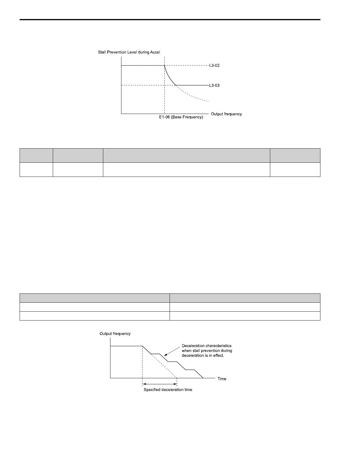
Figure 5.73 shows the Stall Prevention during deceleration function.
Figure 5.73 Stall Prevention Operation during Deceleration
2 : Intelligent (Ignore Decel Ramp)